Compressor with radial sealing structure
A compressor and sealing groove technology, which is applied in the field of compressors, can solve the problems of increasing machining costs and unavoidable cutting tools, and achieves the effects of reducing machining costs and simplifying machining and forming.
- Summary
- Abstract
- Description
- Claims
- Application Information
AI Technical Summary
Problems solved by technology
Method used
Image

Examples
Embodiment 1
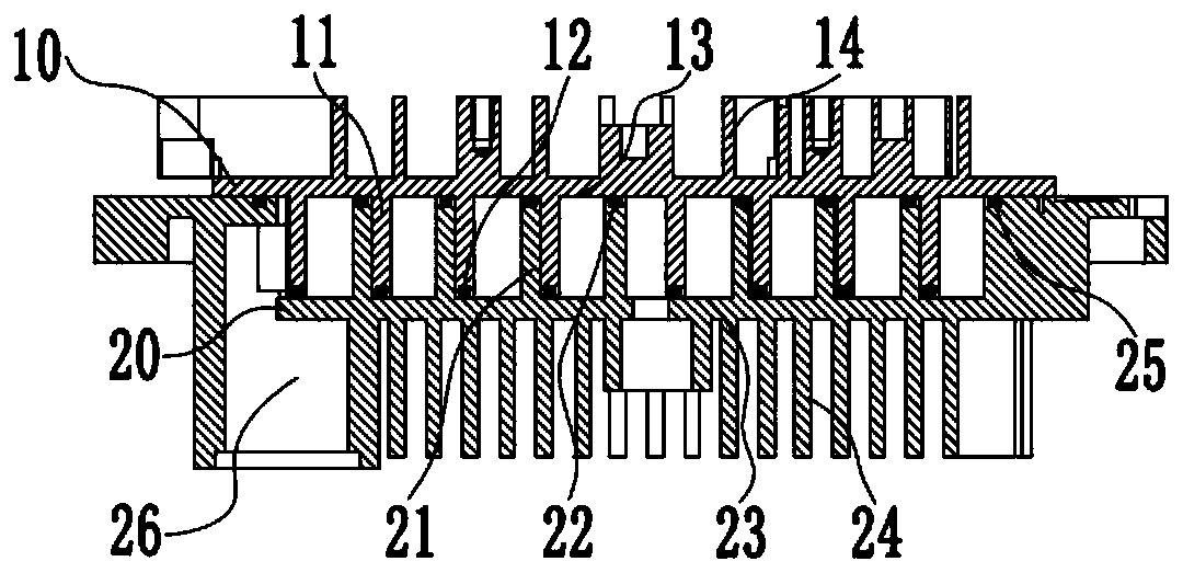
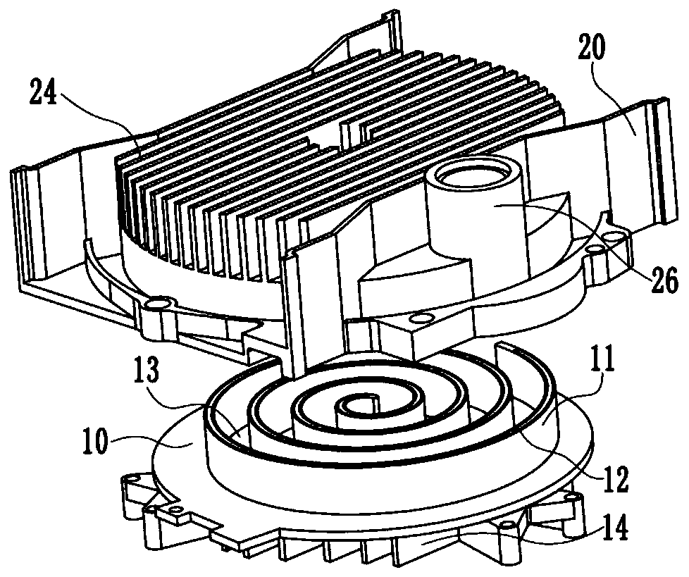
[0109] Such as figure 1 and figure 2 As shown in , the pump body of the scroll air compressor includes a movable scroll 10 and a fixed scroll 20 . The moving scroll 10 includes: the moving scroll plate 11, the moving disk sealing strip 12, the moving disk substrate 13 and the moving disk cooling fins 14; , the static disk substrate 23 , the static disk cooling fins 24 and the static disk shock-absorbing sealing strip 25 .
[0110] Further, the movable scroll 10 and the fixed scroll 20 are engaged with each other to form a plurality of crescent-shaped compression chambers.
[0111] Further, the design of intermittent fit is adopted between the movable scroll plate 11 on the movable scroll 10 and the fixed scroll plate 21 on the fixed scroll 20 to avoid the internal friction of the movable scroll 11 Abrasion occurs between the side surface and the outer surface of the stationary scroll 21 or the outer surface of the movable scroll plate 11 and the inner surface of the stati...
Embodiment 2
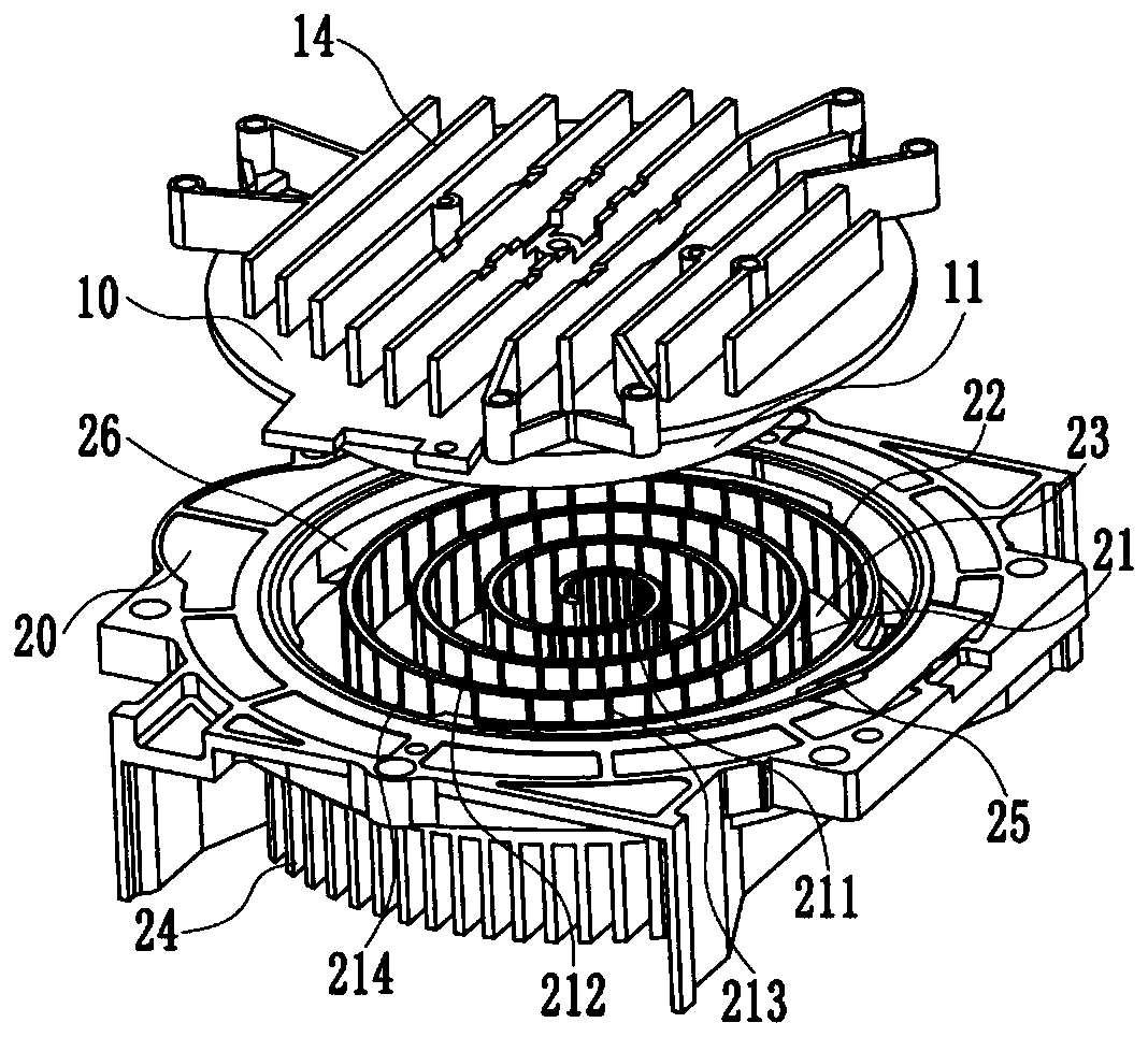
[0120] Such as Figure 4 As shown, labyrinth grooves 211 / 212 / 213 / 214 are opened on the scroll plate 21 of the fixed scroll 20 .
[0121] Further, the labyrinth grooves 211 / 212 / 213 / 214 are formed by drilling and / or reaming and / or boring and / or a combination of one or more processing techniques.
[0122] Further, the automatic processing machine tool sets the processing positioning program according to the spiral line of the movable scroll 10 or the fixed scroll 20 .
[0123] Further, the machining tool starts to process various shapes of labyrinth grooves 211 / 212 / 213 / 214.
[0124] Further, the machining tool gradually processes a plurality of labyrinth grooves 211 / 212 / 213 / 214 along the spiral line according to the set program.
[0125] Further, the labyrinth groove 211 / 212 / 213 / 214 can only be opened on the scroll plate of one of the movable scroll 10 or the fixed scroll 20, so as to avoid the friction between the movable scroll 10 and the fixed scroll 20. Scratching an...
Embodiment 3
[0140] Such as Figure 9-14 As shown, the labyrinth groove 211a inside the high pressure zone, the labyrinth groove 211b outside the high pressure zone, the labyrinth groove 212a inside the medium pressure zone, the labyrinth groove 212b outside the medium pressure zone, the labyrinth groove 213a inside the low pressure zone, the labyrinth groove 213b outside the low pressure zone, and the labyrinth groove 213b outside the low pressure zone. The depth H of the labyrinth groove 214a inside the low pressure area and the labyrinth groove 214b on the outer side of the ULV area 1 all the same.
[0141] Further, the depth H of the labyrinth groove 211 / 212 / 213 / 214 1 Both are 1 / 2 to 1 times the height H of the scroll plate, that is, H / 2≤H 1 ≤H.
[0142] Further, the depth of the labyrinth grooves 211 / 212 / 213 / 214 can be selected according to the sealing performance of the dynamic and static discs and the time-consuming machining.
[0143] Further, if the sealing performance require...
PUM
 Abstract
Description
Claims
Application Information
 - R&D
- Intellectual Property
- Life Sciences
- Materials
- Tech Scout
- Unparalleled Data Quality
- Higher Quality Content
- 60% Fewer Hallucinations
Browse by: Latest US Patents, China's latest patents, Technical Efficacy Thesaurus, Application Domain, Technology Topic, Popular Technical Reports.
© 2025 PatSnap. All rights reserved.Legal|Privacy policy|Modern Slavery Act Transparency Statement|Sitemap|About US| Contact US: help@patsnap.com