
A vibration-damping buffer structure and missile-borne equipment applied to sensitive devices

A technology of sensitive devices and buffer structures, which is applied in the field of inertial navigation systems, can solve the problems of poor impact resistance and restriction of guided munitions, and achieve the effects of avoiding pulling or even falling off failure, improving absorption effect, and improving the stress state of low frequency bands

Active Publication Date: 2021-04-27
XIAN MICROELECTRONICS TECH INST
View PDF5 Cites 0 Cited by
  • Summary
  • Abstract
  • Description
  • Claims
  • Application Information

AI Technical Summary

Problems solved by technology

At the same time, the traditional anti-shock strategy is only developed for the core device inertial measurement unit, and does not consider vibration damping and buffering from the perspective of system-local-device, so the anti-shock effect is not good
High overload impact protection technology is still the technical bottleneck restricting guided munitions

Method used


Image

  • A vibration-damping buffer structure and missile-borne equipment applied to sensitive devices
  • A vibration-damping buffer structure and missile-borne equipment applied to sensitive devices
  • A vibration-damping buffer structure and missile-borne equipment applied to sensitive devices

Examples


Embodiment Construction

[0028] In order to make the purpose, technical solutions and advantages of the embodiments of the present invention clearer, the technical solutions of the present invention will be clearly and completely described below in conjunction with the accompanying drawings. Obviously, the described embodiments are part of the embodiments of the present invention, not all of them. the embodiment. Based on the embodiments of the present invention, all other embodiments obtained by persons of ordinary skill in the art without making creative efforts belong to the protection scope of the present invention.

[0029]It should be noted that the terms "first" and "second" in the description and claims of the present invention and the above drawings are used to distinguish similar objects, but not necessarily used to describe a specific sequence or sequence. It is to be understood that the data so used are interchangeable under appropriate circumstances such that the embodiments of the invent...


PUM


Abstract

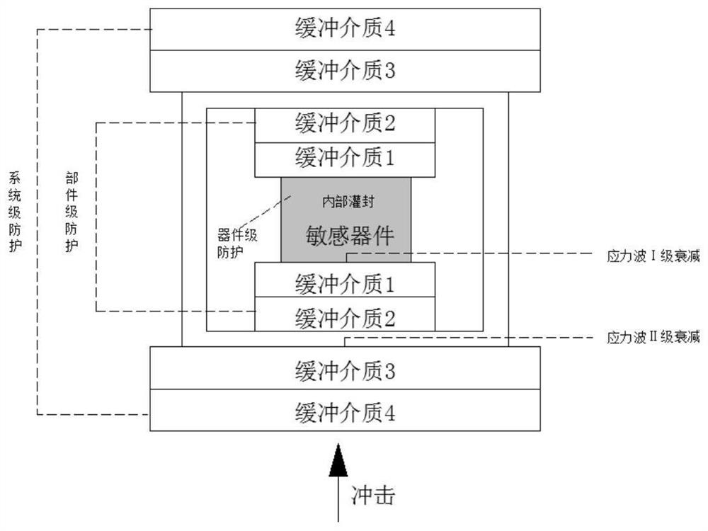
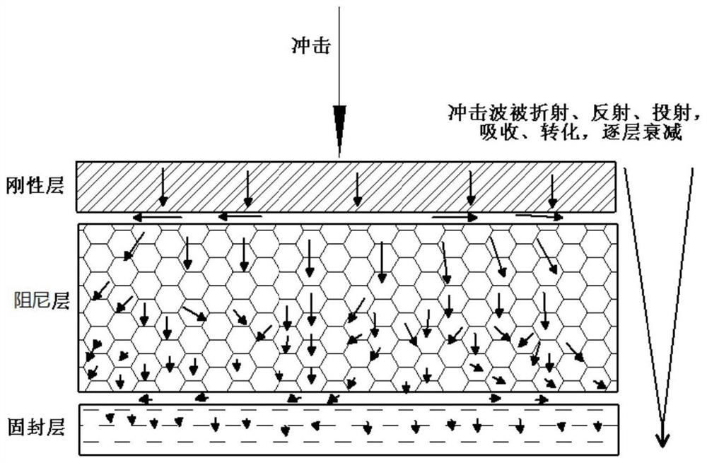
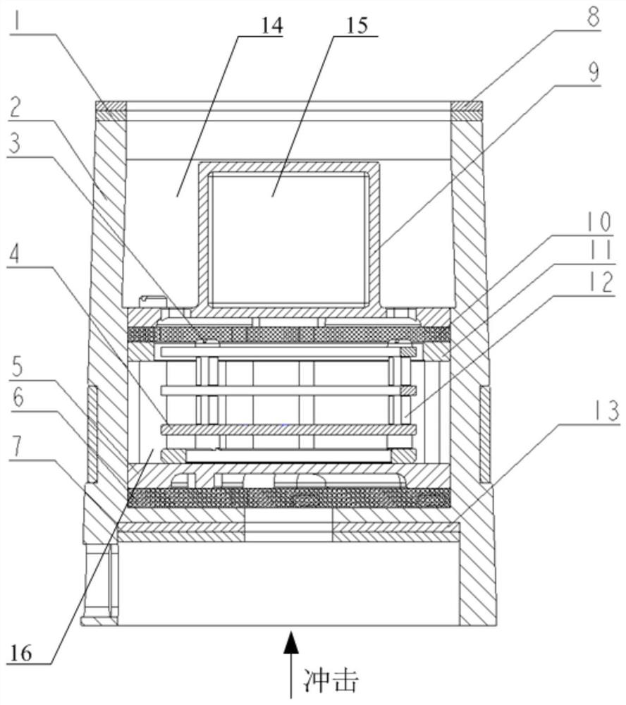
The invention discloses a vibration-reducing buffer structure and missile-borne equipment applied to sensitive devices. The protection is carried out from the perspectives of the core sensitive device level, the component level and the system level. Aiming at high and low frequency bandwidth impact energy, high-impedance filter absorbing materials are selected. Composite materials, the structure adopts a system structure vibration reduction method combining multi-layer dielectric vibration isolation and multi-component vibration reduction, which improves the absorption effect of high and low frequency impact energy, and is suitable for the protection of sensitive devices. The direction of impact force is from the system level to the component level. , and then to the core sensitive device level, through the introduction of the shock stress wave, it attenuates step by step, and finally attenuates to meet the shock resistance requirements of the core inertial device. Partial epoxy compound is used for overall potting and reinforcement to improve the overall rigidity and strength of key core components. Flexible connections are used for the connection of core sensitive components to ensure the displacement buffer tolerance of core sensitive components and avoid damage caused by too strong connection rigidity. Partial devices are pulled or even fall off under impact and fail.

Description

technical field [0001] The invention belongs to the field of inertial navigation systems, and in particular relates to a shock-absorbing buffer structure and missile-borne equipment applied to sensitive devices. Background technique [0002] In order to meet the development needs of guided munitions in the direction of high precision, miniaturization and low cost, countries are currently vigorously developing integrated control units that integrate guidance and control. Most of the inertial devices such as accelerometers and gyroscopes in the inertial measurement unit (IMU) It is a mechanical type with a cavity or cantilever structure, which is easily affected by impact loads, resulting in the possibility of device performance degradation or even failure, and is the most vulnerable part of the product. The traditional anti-shock method is to apply a shock absorber. This method has a good attenuation effect on the medium and low frequency shock energy, but it cannot effective...

Claims


Application Information

Patent Timeline
Patent Type & Authority Patents(China)
IPC IPC(8): F16F7/12G01C21/16
CPCF16F7/12F16F7/121F16F7/128G01C21/16
Inventor 阎彬龚荣文张波左君龙
Owner XIAN MICROELECTRONICS TECH INST
Learn More