
Line-scanning X-ray tube digital imaging detection device

A technology of digital imaging and detection device, applied in the direction of using radiation for material analysis, etc., can solve the problems of low detection efficiency, low detection efficiency, affecting detection effect, etc.

Pending Publication Date: 2019-10-22
DANDONG HUARI SCIENCE ELECTRIC CO LTD
View PDF0 Cites 10 Cited by
  • Summary
  • Abstract
  • Description
  • Claims
  • Application Information

AI Technical Summary

Problems solved by technology

One of the existing technologies so far is the traditional film detection. Whether it is domestic or foreign products, most of the imaging methods use film imaging. This method has disadvantages such as on-site filming, film darkroom image processing, film evaluation, and detection report lag. Process conditions, not only poor detection sensitivity, but also high labor intensity, low detection efficiency, high detection cost, and because the detection results cannot be judged in real time, its lag seriously affects the construction progress, and the film has a short archiving time, and the error rate The other is the imaging plate-type X-ray pipeline inspection technology in the experimental stage. The imaging plate-type X-ray pipeline inspection technology adopts chain-type guide transmission, or self-made track guide, which causes large jitter during transmission and low precision of guide transmission. The effect is poor and the detection sensitivity is low, which greatly affects the detection effect. Since the imaging plate detection is a static shot, take a picture at a position, the detection speed is slow and the time is long, and the detection efficiency is not high. In addition, because the imported imaging plate is used As a detection X-ray receiver, the cost price is too high, which increases the cost burden of the enterprise, which is not conducive to widespread application

Method used


Image

  • Line-scanning X-ray tube digital imaging detection device
  • Line-scanning X-ray tube digital imaging detection device
  • Line-scanning X-ray tube digital imaging detection device

Examples


Embodiment Construction

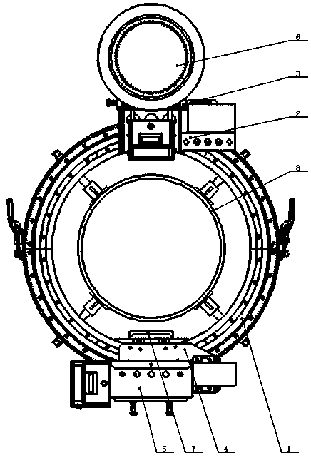
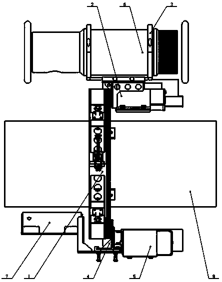
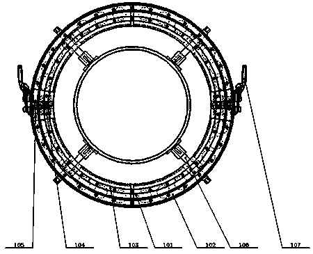
[0029] Such as Figure 1-Figure 12 A line scanning type X-ray pipeline digital imaging detection device is shown, including a detection equipment fixing ring 1, a X-ray machine moving base 2, a X-ray machine fixing device 3, a detector moving base 4, a detector dismounting device 5, a X-ray machine 6, Line array device 7; wherein the testing equipment fixing ring 1 is fixed outside the center position of the butt weld of the steel pipe 8 to be tested, and the X-ray machine moving base 2 is connected with the arc guide rail 103 through the arc guide rail slider 106 and fixed on the testing equipment. On the upper end of the ring 1, the drive gear 1 205 is engaged with the arc rack 102 to complete the drive transmission, and the detector moving base 4 is connected to the arc guide rail 103 through the arc guide rail slider 2 406 and fixed on the detection equipment fixed ring 1 At the lower end, the drive gear 2 405 is engaged with the arc-shaped rack 102 to complete the drive t...


PUM


Abstract

The invention discloses a line-scanning X-ray tube digital imaging detection device, which comprises a detection device fixation ring, a ray machine mobile base, a ray machine fixation device, a detector mobile base, a detector dismounting device, a ray machine and a linear array detector. The detection device fixation ring is arranged outside a tested steel tube; the ray machine and the linear array detector are arranged at the upper and lower ends of the detection device fixation ring respectively, move along an arc guide rail through an arc toothed bar and move circularly outside of the detected steel tube, and meanwhile, enable X-ray for synchronous flaw detection to finish real-time imaging detection of pipeline butt welding seams. The detection device not only overcomes many disadvantages of traditional film detection technology, improves detection efficiency, but also overcomes the defects of low guidance accuracy and poor detection effect of the imaging plate X-ray pipeline inspection technology, greatly reduces cost and is more suitable for wide popularization and application.

Description

technical field [0001] The invention relates to an X-ray detection device, in particular to a line-scan type X-ray pipeline digital imaging detection device. Background technique [0002] At present, natural gas and oil pipelines are welded by multiple steel pipes. In order to ensure the welding quality, X-ray non-destructive testing should be carried out on the connection weld between every two steel pipes. One of the existing technologies so far is the traditional film detection. Whether it is domestic or foreign products, most of the imaging methods use film imaging. This method has disadvantages such as on-site filming, film darkroom image processing, film evaluation, and detection report lag. Process conditions, not only poor detection sensitivity, but also high labor intensity, low detection efficiency, high detection cost, and because the detection results cannot be judged in real time, its lag seriously affects the construction progress, and the film has a short arch...

Claims


Application Information

Patent Timeline
IPC IPC(8): G01N23/04
CPCG01N23/04
Inventor 王鹤王浩史秀峰罗宏宾谭晓超王成刘广大党斌刘晶宋俐刘方秋王鹏孙喆
Owner DANDONG HUARI SCIENCE ELECTRIC CO LTD
Learn More