Low-complexity millimeter wave multicast beamforming method

A beamforming, low-complexity technology, applied in the field of millimeter-wave wireless communication, can solve problems such as high computational complexity

Active Publication Date: 2019-10-22
SOUTHEAST UNIV
View PDF4 Cites 3 Cited by
  • Summary
  • Abstract
  • Description
  • Claims
  • Application Information

AI Technical Summary

Problems solved by technology

However, the complexity of the algorithm is proportional to the number of antennas, and millimeter-wave multicast communication usually uses a large-scale antenna array, which has a high computational complexity

Method used


Image

  • Low-complexity millimeter wave multicast beamforming method
  • Low-complexity millimeter wave multicast beamforming method
  • Low-complexity millimeter wave multicast beamforming method

Examples


Embodiment Construction

[0070] The technical solutions of the present invention will be further described in detail below in conjunction with the accompanying drawings and embodiments.

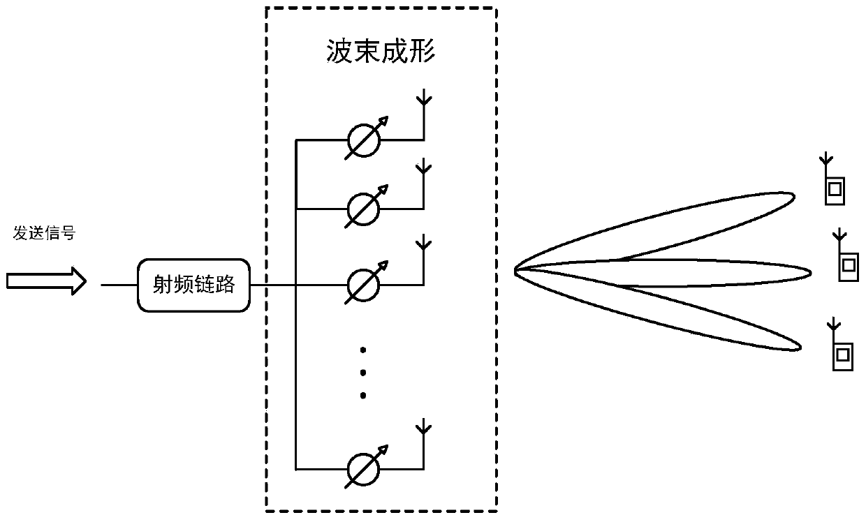
[0071] (1) if figure 1 As shown, the communication system model used in the present invention is described as follows:

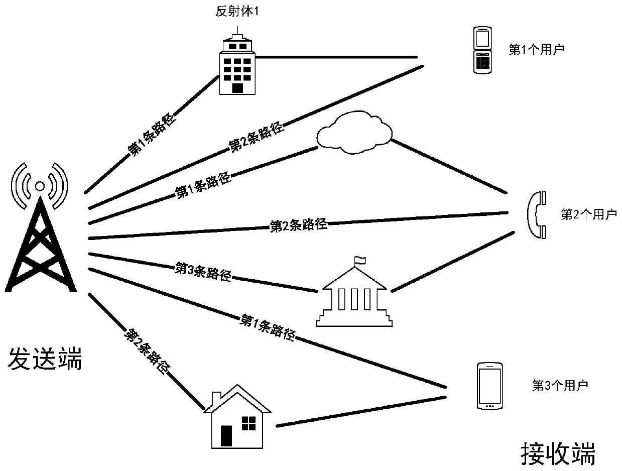
[0072] The analog beamforming architecture equipped with a large-scale antenna array is adopted at the signal transmitting end, and multiple users receive omnidirectionally with a single antenna at the receiving end. array to send. The signal is transmitted to the receiving end through the wireless channel between the sending end and different users, and the final signal is obtained after being received by a single array element antenna at the receiving end. The antenna array at the sending end is a uniform linear array with a half-wavelength array element spacing, and the number of array elements is N BS . Then the received signal can be expressed as:

[0073]

[0074] Among them, P, h k ...


PUM


Abstract

The invention discloses a low-complexity millimeter wave multicast beamforming method. According to the method, multicast communication for multiple users is realized by designing a beam forming vector. The millimeter wave antenna array is divided into a plurality of sub-arrays, each sub-array forms a sub-wave beam which points to different users, and phase shift factors are added to different sub-arrays to improve the design flexibility. Through the molecular array, the number of variables needing to be optimized is greatly reduced, and the calculation complexity is greatly reduced while theperformance is close to that of an existing scheme.

Description

technical field [0001] The invention belongs to the field of millimeter-wave wireless communication, and relates to a low-complexity millimeter-wave multicast beamforming method. Background technique [0002] With the popularization of mobile intelligent terminal equipment, people's demand for wireless communication is increasing, and the requirements for communication quality are also getting higher and higher. Millimeter wave communication (30GHz-300GHz) has attracted widespread attention because of its rich spectrum resources and high-speed transmission rate. However, due to the high loss of the high-frequency signal transmission path and the high cost of hardware design, the traditional all-digital beamforming architecture is no longer suitable for millimeter-wave communication systems, and a hybrid beamforming architecture is usually used to form high-directional beam compensation through analog beamforming Path loss, reducing mutual interference of multiple data strea...

Claims


Application Information

Patent Timeline
Patent Type & Authority Applications(China)
IPC IPC(8): H04B7/06H04B7/0452H04B7/0408H04B17/391
CPCH04B7/0617H04B7/0408H04B7/0452H04B17/391
Inventor 戚晨皓李朝辉陈康建
Owner SOUTHEAST UNIV
Why Eureka
Try Eureka