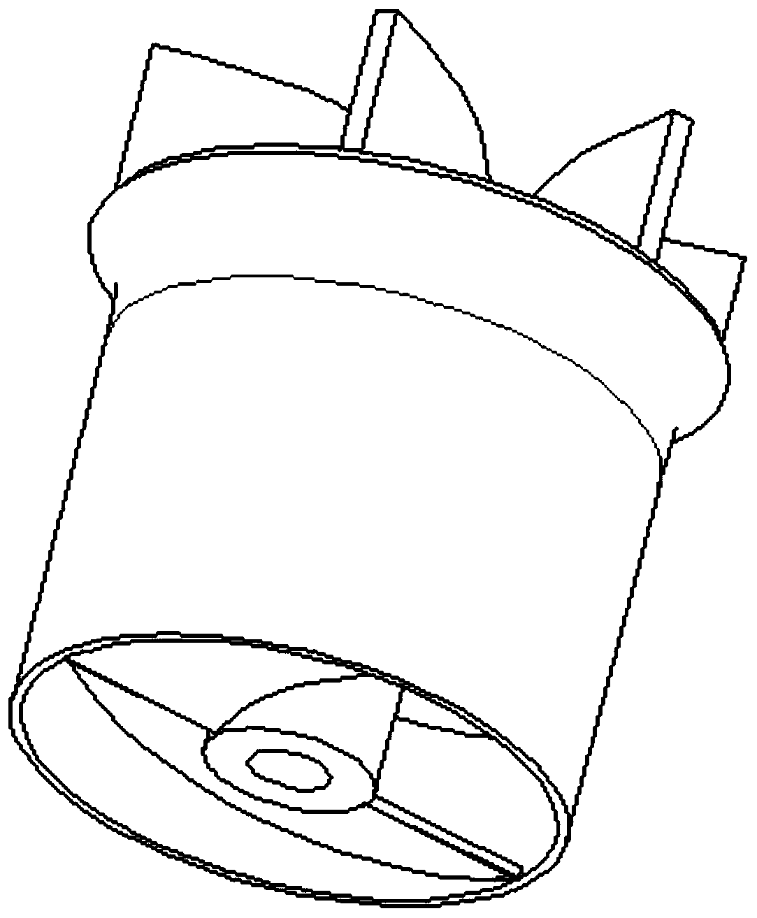
Water pump impeller for dish washing machine
A water pump impeller, dishwasher technology, applied in the direction of pumps, parts of pumping devices for elastic fluids, pump elements, etc., can solve the problems of reduced efficiency, poor stability, insufficient improvement effect, etc., to achieve load capacity Sufficient, high efficiency, stable flow effect
- Summary
- Abstract
- Description
- Claims
- Application Information
AI Technical Summary
Problems solved by technology
Method used
Image
Examples
Embodiment 1
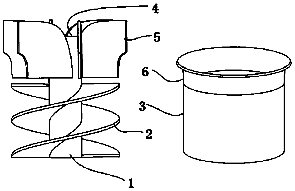
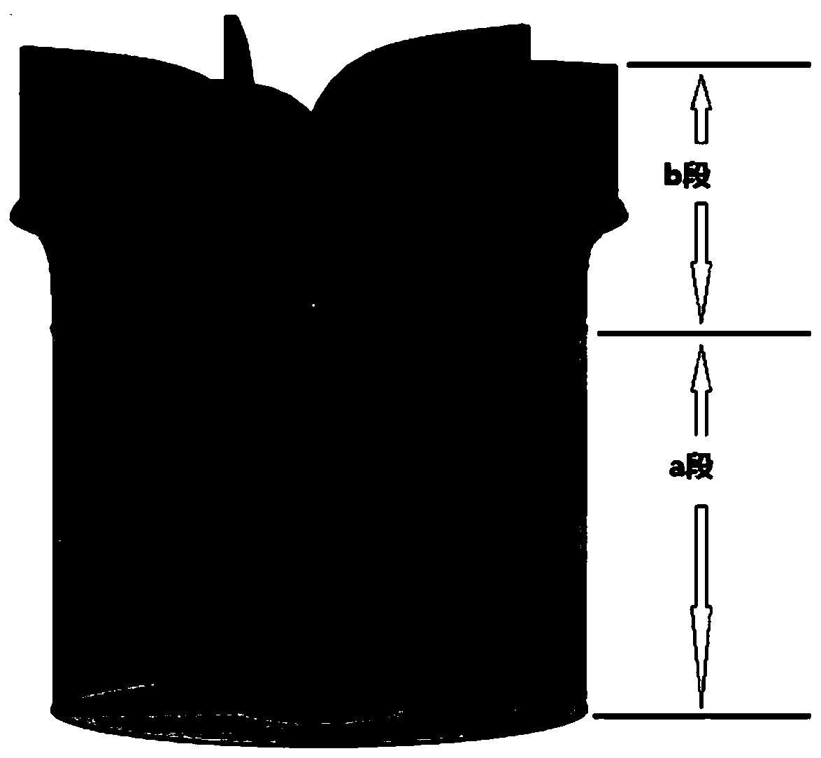
[0062] Embodiment one of the present invention is attached image 3 , attached Figure 3-1 , the "water intake section" is composed of a first-level "water flow delivery unit" with a continuous and uninterrupted long spiral flow channel. 1. Water intake section: see attachment diagram 2-1 , the present invention is a water pump impeller for dishwashers, and the water pump impeller includes a section (water intake section) and b section (throwing out wheel). See attached image 3 , Section a includes a hollow central shaft 1 for passing through the motor shaft, and the "central shaft 1" is provided with a flat installation position, which is convenient for fastening with the motor shaft. Several helical blades 2 are arranged on the outer side of the shaft body of the "central shaft 1", and each "helical blade 2" is divided by 360 degrees of the circumference by the angle obtained by 'the number of blades' (called the array angle, and the number of blades is N , then the arra...
Embodiment 2
[0066] Embodiment two of the present invention is attached Figure 4 , attached Pic 4-1 , constitute "water intake section" by discontinuous two-stage short spiral flow path 'water flow conveying unit', and "throwing out wheel" is the same as embodiment one. See attached Figure 4, define the lower-level short spiral channel 'water flow delivery unit' as a1, and the upper level of a1 as a2. The "water intake section" of the second embodiment includes a hollow central shaft 1 for passing through the motor shaft, and the "central shaft 1" is provided with a flat installation position, which is convenient for fastening with the motor shaft. Several a1 section blades 21 and several a2 section blades 22 are arranged outside the shaft body of the "central shaft 1", and the blades 21 and blades 22 are divided by 360 degrees of the circumference by the angle obtained from the 'number of blades' of the section (referred to as The array angle, assuming that the number of blades is N...
Embodiment 3
[0070] Embodiment three of the present invention is attached Figure 5 , attached Figure 5-1 , the "water intake section" is composed of the first-level "water flow delivery unit" + "long empty section" of the short flow channel, that is, the first-level short flow channel is composed of the "short blade group" + "central axis" + "cover cylinder", and the blades Above the group is empty. "Throwing out the wheel" is the same as embodiment one. See attached Figure 5 , The "water intake section" of the third embodiment includes a hollow central shaft 1 for passing through the motor shaft, and the "central shaft 1" is provided with a flat installation position, which is convenient for fastening with the motor shaft. Several blades 2 are arranged on the outside of the "central axis 1" shaft body, and each "blade 2" is divided by 360 degrees of the circumference by the angle obtained by the 'number of blades' (called the array angle, if the number of blades is N, then the array...
PUM
 Abstract
Description
Claims
Application Information
 - R&D
- Intellectual Property
- Life Sciences
- Materials
- Tech Scout
- Unparalleled Data Quality
- Higher Quality Content
- 60% Fewer Hallucinations
Browse by: Latest US Patents, China's latest patents, Technical Efficacy Thesaurus, Application Domain, Technology Topic, Popular Technical Reports.
© 2025 PatSnap. All rights reserved.Legal|Privacy policy|Modern Slavery Act Transparency Statement|Sitemap|About US| Contact US: help@patsnap.com


