A solid waste incinerator

A technology for solid waste and incineration devices, applied in incinerators, combustion types, combustion methods, etc., can solve the problems of blockage, increase process, and long combustion time, and achieve the effect of increasing contact area, increasing gap, and facilitating oxygenation

Active Publication Date: 2020-11-06
NANJING PUSI ENVIRONMENTAL TECH CO LTD
View PDF6 Cites 0 Cited by
  • Summary
  • Abstract
  • Description
  • Claims
  • Application Information

AI Technical Summary

Problems solved by technology

[0003] However, the currently incinerated solid waste produces leachate due to long-term stacking. When the solid waste is put into the interior of the combustion equipment, some wet waste with leachate will be put in directly, which will cause insufficient combustion, and the garbage with leachate will be covered. The burning garbage will affect the burning of the previous batch of garbage, and the drying pretreatment before burning will increase the process and consume heat energy. Garbage burning is a continuous process, and garbage needs to be added to the burning equipment one after another. Too much The rubbish is squeezed inside the combustion equipment, and the burning ash is squeezed, which leads to the lack of oxygen inside, resulting in long burning time and insufficient combustion. The interior of the traditional combustion equipment is generally a closed space, and the burned garbage is not easy to clean up in time. , easy to cause clogging and insufficiently burned garbage pushing problems

Method used


Image

  • A solid waste incinerator
  • A solid waste incinerator
  • A solid waste incinerator

Examples


Embodiment Construction

[0024] In order to make the technical means, creative features, goals and effects achieved by the present invention easy to understand, the present invention will be further described below in conjunction with specific embodiments.

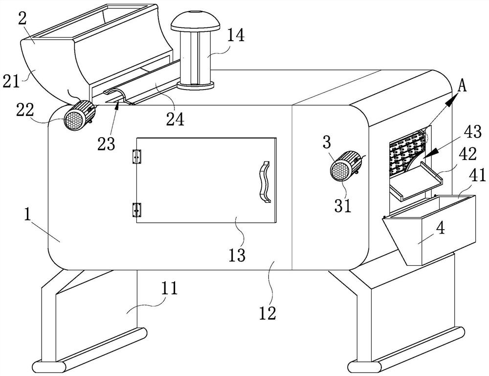
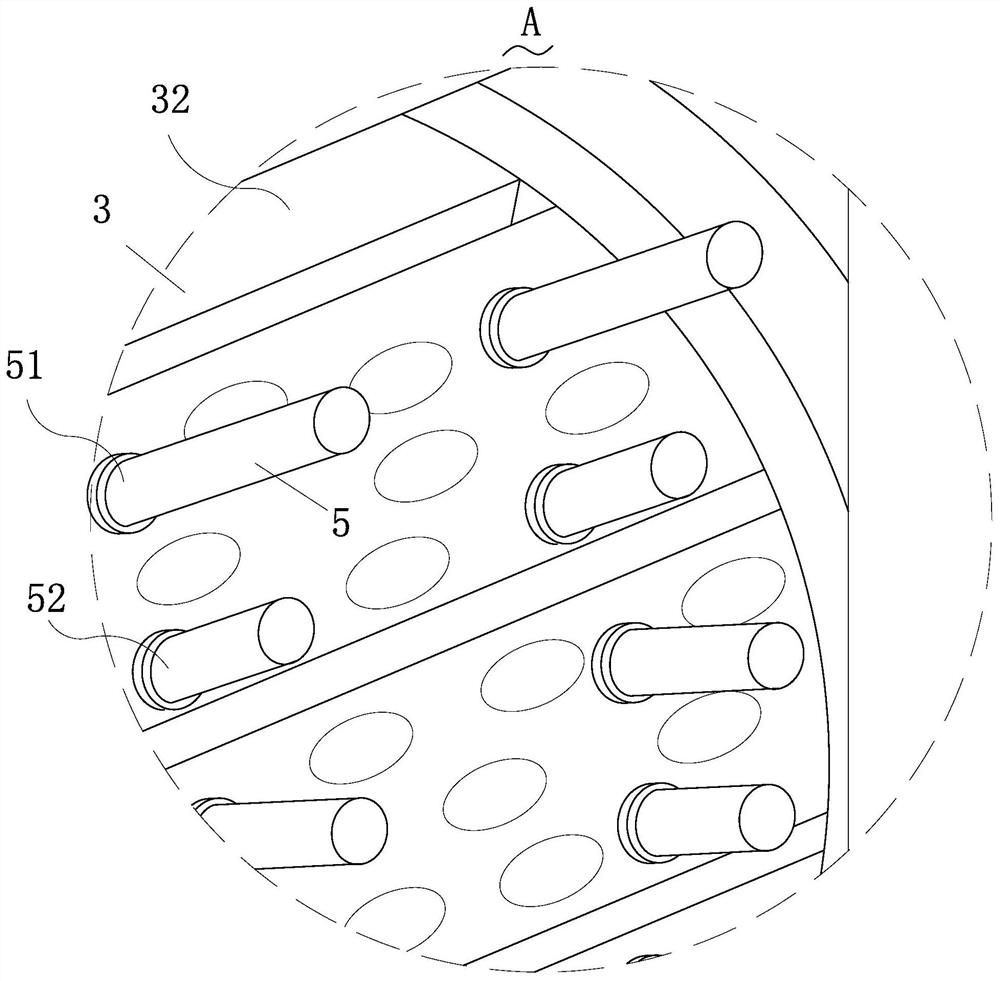
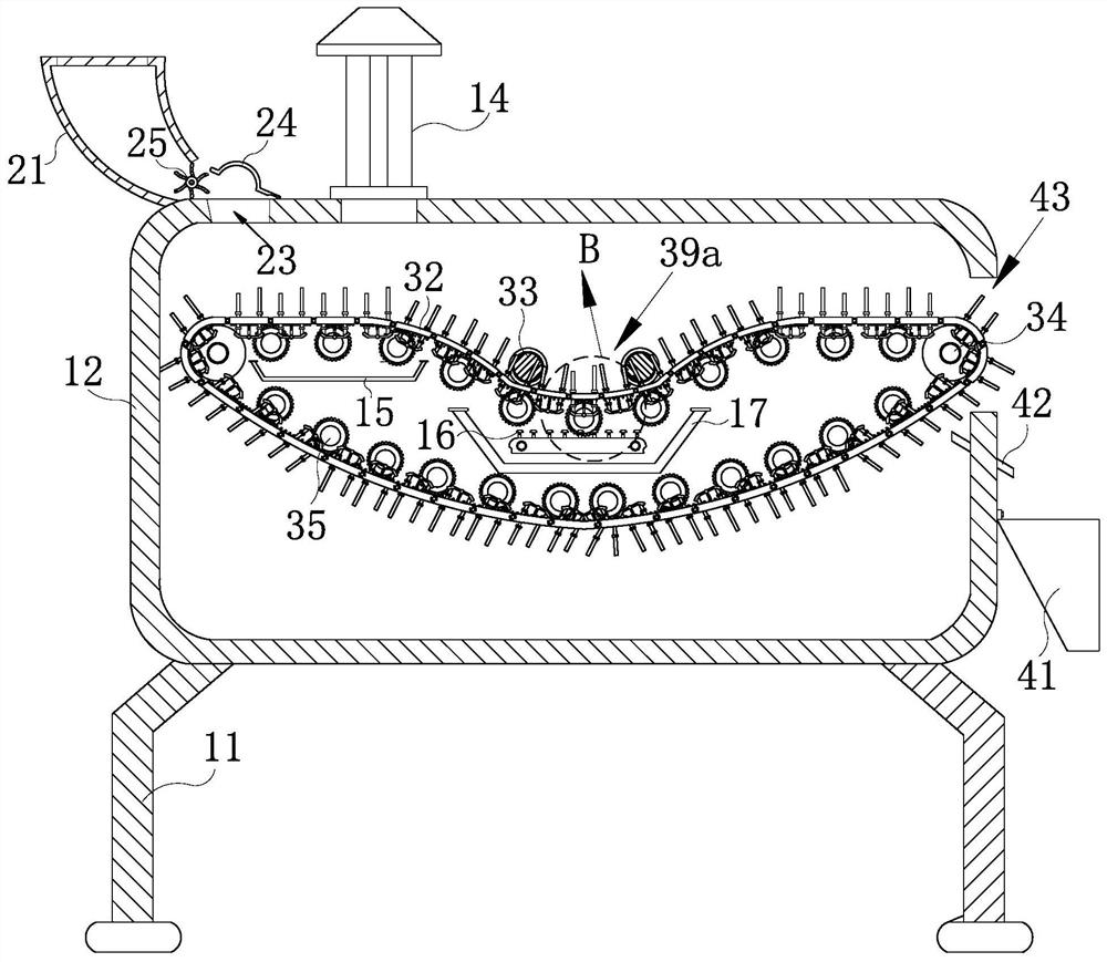
[0025] like Figure 1-Figure 7 As shown, a solid waste incineration device according to the present invention includes a main body mechanism 1, a feeding mechanism 2, a driving mechanism 3, a feeding mechanism 4, and a combustion-supporting mechanism 5; The top of the main mechanism 1 supported by the mechanism is equipped with the feeding mechanism 2 for realizing the loading of solid waste and avoiding garbage blockage, and the side wall of the main mechanism 1 is away from the loading mechanism 2. There is the unloading mechanism 4 for collecting insufficiently burned garbage, and the inside of the main mechanism 1 is horizontally installed with the bottom of the loading mechanism 2 and one side of the unloading mechanism 4 for The drive mecha...


PUM


Abstract

The invention relates to the field of waste incineration, in particular to a solid waste incineration device. The solid waste incineration device comprises a main body mechanism, a feeding mechanism,a driving mechanism, a discharging mechanism and a combustion-supporting mechanism; the interior of a box body is rotationally connected to crawler belts with U-shaped cross sections through driving discs, first supporting rods and second supporting rods with different lengths are connected to the plurality of crawler belts in the transverse direction and the longitudinal direction in a sliding mode at equal intervals; when the solid waste is located on the surfaces of the first supporting rods and the second supporting rods at the bottom of the feeding mechanism, the distance between the solid waste and a burning groove is far, so that the primary drying of the wet waste is realized; when the waste reaches the burning groove, the combustion of the waste is realized, the included angle between every two adjacent first supporting rod and the second supporting rod is small so that the waste can fall onto the surface of the crawler belts for sufficient combustion; and the waste with insufficient combustion can fall off from a discharging port, the two adjacent the first supporting rod and the second supporting rod is increased at the corresponding driving disc, and therefore the wastewhich is not completely combusted and sand stone can be favorably prevented from falling into a material receiving hopper.

Description

technical field [0001] The invention relates to the field of waste incineration, in particular to a solid waste incineration device. Background technique [0002] Solid waste refers to solid, semi-solid, and gaseous items placed in containers that lose their original use value or have not lost their use value but are discarded or abandoned during production, living and other activities. , Articles and substances that are included in waste management according to administrative regulations. Liquid wastes that cannot be discharged into water bodies and gaseous substances placed in containers that cannot be discharged into the atmosphere. At present, the treatment of solid waste is mainly based on landfill and incineration. [0003] However, the currently incinerated solid waste produces leachate due to long-term stacking. When the solid waste is put into the interior of the combustion equipment, some wet waste with leachate will be put in directly, which will cause insuffici...

Claims


Application Information

Patent Timeline
Patent Type & Authority Patents(China)
IPC IPC(8): F23G5/04F23G5/08F23G5/44
CPCF23G5/04F23G5/08F23G5/444F23G2201/10
Inventor 汪泽洋程勇
Owner NANJING PUSI ENVIRONMENTAL TECH CO LTD
Why Eureka
Try Eureka