Unit plant and solid electric heat storage unit of combined structure

A technology of unit unit and combined structure, which is applied in the direction of fluid heaters, heat storage equipment, heat storage heaters, etc., can solve the unfavorable heat exchange efficiency of solid heat storage boilers, improve heat storage capacity, and do not consider the convenience of equipment maintenance and maintenance Problems such as internal thermal storage heat exchange and ventilation air path are too long, so as to simplify the process and difficulty of design and construction, reduce personnel and costs, and improve system reliability.

Pending Publication Date: 2019-10-25
周封
View PDF3 Cites 0 Cited by
  • Summary
  • Abstract
  • Description
  • Claims
  • Application Information

AI Technical Summary

Problems solved by technology

[0002] The current solid heat storage boilers generally have an integral structure. The heat storage body and the overall assembly are carried out at the implementation site. The main problems are as follows: 1) Some large-scale construction and testing equipment need to be transported to the site, and the site needs more construction technicians, long construction period and high construction cost; 2) With the difference in total installed capacity, the capacity of a single unit lacks a standardized design, and the heat exchange and ventilation air path of the internal heat storage body is too long, which is not conducive to improving the exchange rate of the solid heat storage boiler. Thermal efficiency, heat storage capacity improvement, etc.; 3) The on-site assembly method will also lead to non-standard components, and there is no replacement of components when problems occur, making maintenance inconvenient; 4) When the capacity of a single unit is too large, once a failure occurs, it needs to be shut down as a whole. It will seriously affect the heat supply effect; 5) Adjusting the heat supply adopts frequency conversion or valve throttling method, which has high cost or large pressure and energy loss; 6) Lack of excessive temperature difference between various parts inside the heat storage body has great impact on heat exchange efficiency, heat storage capacity, Consideration or measures for the impact of service life and other aspects; 7) The convenience of equipment maintenance and maintenance is not considered, etc.
Although it is convenient to realize capacity expansion, first, the partition wall is used to block the air circulation between each heating compartment; second, the resistance heating unit and the heat storage body are located in two different spaces; third, the upper pipe and the bottom pipe are adopted Multiple sets of pipelines run through the whole machine, and each set of pipelines has a frequency conversion fan
The area is large and the cost is high, which does not solve the above problems

Method used


Image

  • Unit plant and solid electric heat storage unit of combined structure

Examples


Embodiment Construction

[0028] Below in conjunction with accompanying drawing, the present invention is described in further detail:

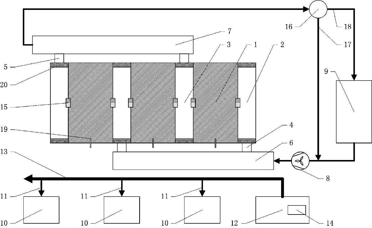
[0029] Such as figure 1 Shown is the top schematic diagram of the solid heat storage unit system structure. The unit unit and the solid electric heat storage unit with combined structure include a unit unit (1), a unit air inlet chamber (2), a unit air outlet chamber (3), an inlet Air outlet (4), air outlet (5), air inlet main pipe (6), air outlet main pipe (7), fan (8), heating equipment (9), unit power distribution cabinet (10), unit inlet line (11 ), main distribution cabinet (12), main busbar (13), intelligent measurement and control device (14), connection mechanism (15), air volume distribution device (16), bypass pipe (17), working pipe (18), temperature Sensor (19), plane insulation wall (20).

[0030] figure 1Among them, there are three unit units (1), which can be numbered sequentially as unit units (1) 1, 2, and 3 from left to right. Unit No. 1 unit (1)...


PUM


Abstract

The invention provides a unit plant and a solid electric heat storage unit of a combined structure and belongs to the technical field of electric heat storage. By way of matching the unit plant, a unit air inlet chamber, a unit air outlet chamber, a unit distribution cabinet and the like as well as by means of an adjacent cross combination structure design of a modular standard part, difference capacities can be combined by the unit plants of different quantities. The solid heat storage unit is quickly mounted in a combined manner, and is maintained, replaced and detached, and the unit plant is repaired and maintained favorably. Meanwhile, an air capacity distribution device is used for distributing outlet air, and the conducting sections of a bypass pipeline and a working pipeline are controlled. The process and difficulty of design and construction are simplified greatly, the internal temperature difference in the unit plant is reduced effectively, the heat accumulating capacity is improved, the system reliability is improved, and the service life of the equipment is prolonged. In addition, the unit plant also has the advantages of being simple in structure, relatively low in cost, reliable to operate, convenient to mount and maintain and the like.

Description

technical field [0001] The invention relates to a solid heat storage unit, in particular to a solid heat storage unit which is composed of a plurality of unit units and can be quickly installed and repaired. The utility model belongs to the technical field of electric heat storage. Background technique [0002] The current solid heat storage boilers generally have an integral structure. The heat storage body and the overall assembly are carried out at the implementation site. The main problems are as follows: 1) Some large-scale construction and testing equipment need to be transported to the site, and the site needs more construction technicians, long construction period and high construction cost; 2) With the difference in total installed capacity, the capacity of a single unit lacks a standardized design, and the heat exchange and ventilation air path of the internal heat storage body is too long, which is not conducive to improving the exchange rate of the solid heat sto...

Claims


Application Information

Patent Timeline
Patent Type & Authority Applications(China)
IPC IPC(8): F24H7/04F24H9/18F24H9/20F28D20/00
CPCF24H7/0416F24H9/1863F24H9/2071F28D20/0056Y02E60/14
Inventor 周封郝婷李伟力刘小可
Owner 周封
Why Eureka
Try Eureka