
An automatic loading and unloading device for perforating charge assembly and its assembly process

A technology of automatic loading and unloading and perforating bullets, which is applied in the direction of ammunition, offensive equipment, weapon accessories, etc., can solve the problem of inability to ensure that the attitude of the liner cover and the projectile body does not change, the insufficient utilization of the potential of the production efficiency of the hydraulic machine, and the The cover and the elastic body are not suitable for the conveyor belt, etc., and the effect of shortening the assembly time, reducing the retrieving time and high production efficiency is achieved.

Active Publication Date: 2021-11-02
BC P INC CHINA NAT PETROLEUM CORP +1
View PDF8 Cites 0 Cited by
  • Summary
  • Abstract
  • Description
  • Claims
  • Application Information

AI Technical Summary

Problems solved by technology

[0004] (1) The pick-up device is designed with a linear motion unit. More linear motion units lead to poor structural rigidity. The linear motion unit is fixed on the frame, and the frame occupies too large a volume. Once the device fails, it cannot be installed manually. material space;
[0005] (2) The conveyor belt transports the liner and projectile. During the conveying process, it cannot be guaranteed that the posture of the liner and projectile will not change. The change of posture is a fatal flaw for the assembly of perforating bullets. Therefore, the liner and projectile Not suitable for conveyor belt delivery;
[0007] (4) When feeding the hydraulic machine, the feeding unit needs to place the projectile and the cover ring with the drug-shaped cover in the hydraulic press in sequence; when feeding the hydraulic machine, the feeding unit needs to respectively place the cover ring and the finished projectile in sequence To the temporary storage mechanism, the form of repeated actions leads to insufficient utilization of the potential of hydraulic press production efficiency

Method used


Image

  • An automatic loading and unloading device for perforating charge assembly and its assembly process
  • An automatic loading and unloading device for perforating charge assembly and its assembly process
  • An automatic loading and unloading device for perforating charge assembly and its assembly process

Examples


Embodiment Construction

[0050] In describing the present invention, it should be understood that the terms "center", "longitudinal", "transverse", "upper", "lower", "front", "rear", "left", "right", " The orientation or positional relationship indicated by "vertical", "horizontal", "top", "bottom", "inner", "outer", "side", "end", "side" etc. is based on the Orientation or positional relationship is only for the convenience of describing the present invention and simplifying the description, and does not indicate or imply that the referred device or element must have a specific orientation, be constructed and operated in a specific orientation, and thus should not be construed as a limitation of the present invention. In addition, the terms "first" and "second" are only used for descriptive purposes, and should not be construed as indicating or implying relative importance or implying the number of indicated technical features. Thus, a feature defined as "first" and "second" may explicitly or implici...


PUM


Abstract

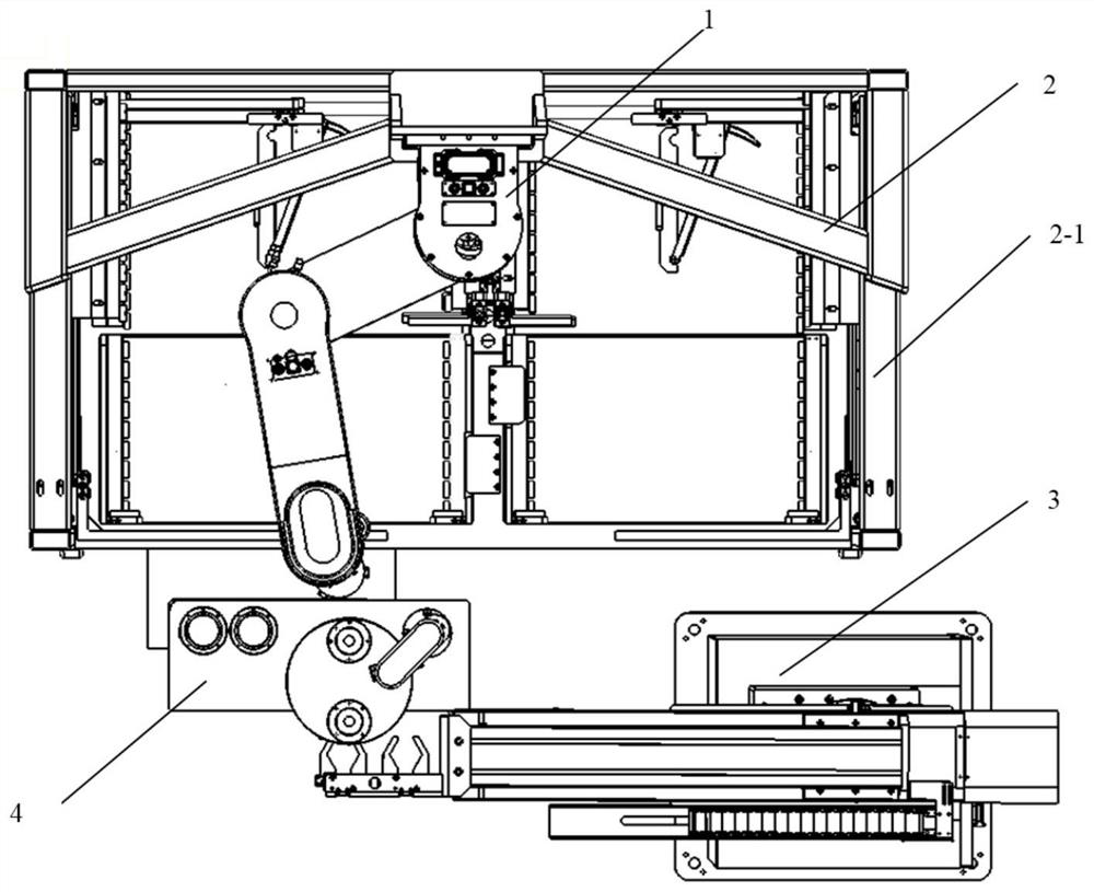
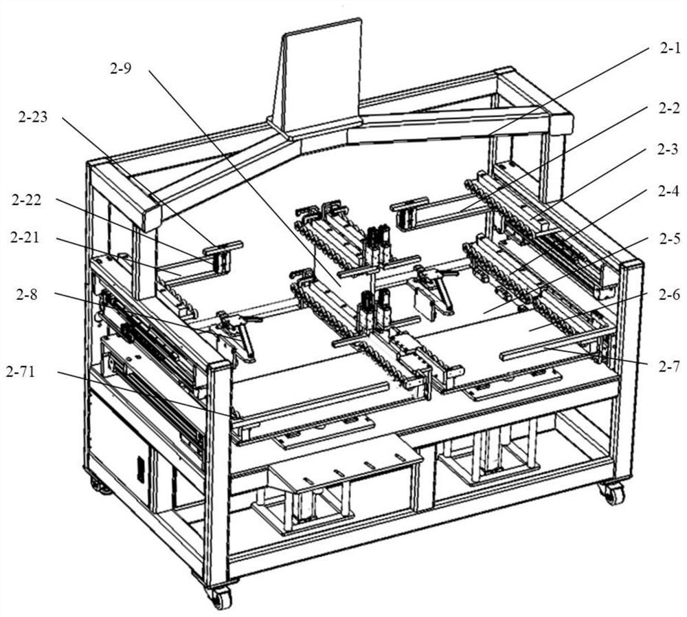
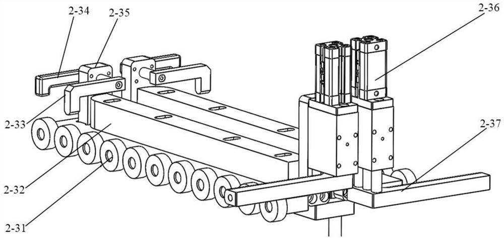
The invention discloses an automatic loading and unloading device for assembling perforating bullets and an assembly process thereof. The handling robot is arranged on the main frame of the feeding and discharging mechanism, the assembly transfer platform is fixed on the main frame through the installation platform, and the assembly transfer platform is used for Assembling and storing the projectile and the cover ring, the material of the feeding mechanism is transported to the discharging mechanism through the lifting mechanism and the horizontal moving mechanism. The locking mechanism is installed on the discharging mechanism, and the discharging mechanism can slide along the movement direction of the horizontal moving mechanism. The lifting mechanism is used to move the pallet vertically; the handling robot is used to carry the projectile and the cover ring between the lifting mechanism and the assembly transfer platform. The stamping robot is fixed on the main frame and has two degrees of freedom in the vertical plane and a Z The degree of freedom of axis rotation; used to carry the assembled projectile body and cover ring between the assembly transfer platform and the hydraulic press. The invention improves equipment safety, reduces occupied area, has simple structure, is easy to control, and can realize high-efficiency assembly and stamping of perforating bullets.

Description

technical field [0001] The invention belongs to the technical field of assembling perforating charges, and particularly relates to an automatic loading and unloading device for assembling perforating charges and an assembling process thereof. Background technique [0002] The perforating charge is a civil explosive device used to penetrate the casing and connect oil and gas and the wellbore in the process of perforating and completing oil and gas wells. Equipment that is partially suppressed and combined into a perforating charge product. At present, most of the domestic perforating charge manufacturers use imported semi-automatic equipment for the pressing of perforating charges. Compared with the highly automated production lines of foreign perforating charges, the domestic perforating charge pressing equipment generally lags behind in the level of automation. . Manually pre-assemble the type cover, explosive and cartridge case into the hydraulic press. This semi-automat...

Claims


Application Information

Patent Timeline
Patent Type & Authority Patents(China)
IPC IPC(8): F42B33/00
CPCF42B33/001F42B33/002
Inventor 程晏桥吴焕龙向旭陈瑞梁雷震贾良平彭科普刘勇刘世平
Owner BC P INC CHINA NAT PETROLEUM CORP
Learn More