
Reflecting device and tunable laser

A reflection device and laser technology, applied in the field of communication, can solve the problems of low temperature, disconnection of tunable lasers, high temperature, etc.

Active Publication Date: 2019-10-25
HISILICON OPTOELECTRONICS CO LIMITED
View PDF6 Cites 2 Cited by
  • Summary
  • Abstract
  • Description
  • Claims
  • Application Information

AI Technical Summary

Problems solved by technology

[0005] In the actual manufacturing process, the suspended structure needs to be connected to other areas of the tunable laser through the support structure to form a support, and cannot be completely disconnected from the tunable laser. Therefore, the temperature of the area close to the support structure is low, and the temperature of the area between the support structures High, the temperature distribution uniformity of the reflection device is poor, which further leads to the deterioration of the reflection performance of the grating, and finally leads to the deterioration of the performance of the tunable laser

Method used


Image

  • Reflecting device and tunable laser
  • Reflecting device and tunable laser
  • Reflecting device and tunable laser

Examples


Embodiment Construction

[0055] Embodiments of the present application provide a reflection device and a tunable laser, which are used to reduce heat loss during thermal tuning, ensure uniform temperature distribution of the reflection device during thermal tuning, and improve thermal tuning efficiency.

[0056] In order to enable those skilled in the art to better understand the solutions of the present application, the following will describe the embodiments of the present application with reference to the drawings in the embodiments of the present application.

[0057] The "first" or "second" mentioned in the present application documents are used to distinguish similar objects, and not necessarily used to describe a specific sequence or sequence. In addition, "comprising" or "having" and any variations thereof mentioned in the application documents are intended to cover non-exclusive inclusion, for example, a process, method, system, product or device comprising a series of steps or units is not ne...


PUM


Abstract

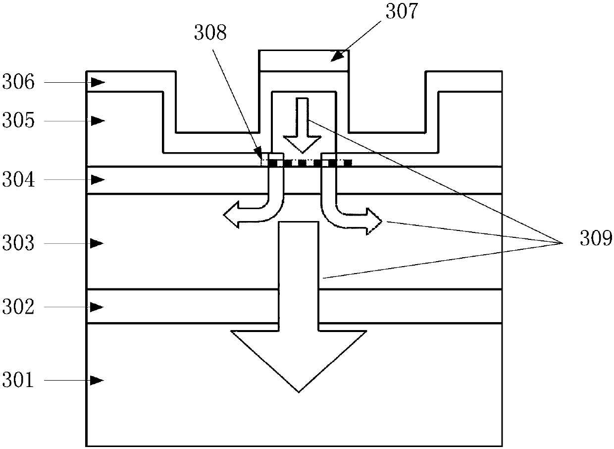
The present application discloses a reflecting device and a tunable laser for ensuring uniform temperature distribution of the reflecting device during thermal tuning and improving the thermal tuningefficiency. The reflecting device comprises a light transmission layer and a ridge protruding from the light transmission layer; a first group of heaters and a second group of heaters isolated from each other are disposed on the surface of the ridge away from the light transmission layer; the light transmission layer on a first side of the ridge is provided with a first support arm and a second support arm isolated from each other, the end surface of the first support arm close to the ridge is a first end surface, the first end surface extends in a direction perpendicular to the ridge to forma first flat plate, and the first group of heaters is at least partially disposed in a region where the surface of the ridge away from the light transmission layer intersects the first flat plate; theend surface of the second support arm close to the ridge is a second end surface, the second end surface extends in a direction perpendicular to the ridge to form a second flat plate, and the secondgroup of heaters is at least partially disposed in a region where the surface of the ridge away from the light transmission layer intersects the second flat plate.

Description

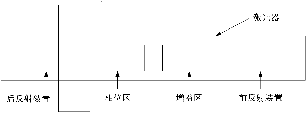
technical field [0001] The present application relates to the communication field, in particular to a reflection device and a tunable laser. Background technique [0002] In the field of optical communication, a tunable laser (tunable laser, TL) refers to a laser whose output wavelength can be adjusted within a certain range. Tunable lasers are mainly used in large-capacity wavelength division multiplexing transmission systems. With the explosive growth of information volume, the scale of the communication market continues to expand rapidly. In order to further increase bandwidth, coherent modulation technology is used and becomes a long-distance optical fiber with a rate of 100G and above. The industry's mainstream solution for transmission. At present, the structure of the more classic tunable laser is as follows: figure 1 As shown, it consists of four sections: the gain section, the front reflector, the back reflector and the phase section. [0003] The tunable laser a...

Claims


Application Information

Patent Timeline
IPC IPC(8): G02F1/01G02B6/124G02B6/122G02B6/12
CPCG02B6/12G02B6/122G02B6/124G02B2006/12104G02B2006/12142G02F1/0147G02F1/01
Inventor 武林陈宏民朱宁军
Owner HISILICON OPTOELECTRONICS CO LIMITED
Learn More