Shaped photovoltaic cell structure and preparation method thereof

A photovoltaic cell and special-shaped technology, applied in photovoltaic power generation, circuits, electrical components, etc., can solve problems such as large dead zone, low battery conversion efficiency, and limited output current, and achieve high effective utilization, beautiful structure, and high conversion efficiency. high effect

Inactive Publication Date: 2019-10-25
西安富阎移动能源有限公司
View PDF1 Cites 0 Cited by
  • Summary
  • Abstract
  • Description
  • Claims
  • Application Information

AI Technical Summary

Problems solved by technology

[0003] The purpose of the present invention is to provide a new type of special-shaped photovoltaic cell structure and its preparation method, to solve the technical problems in the prior art that the output current of the special-shaped photovoltaic cell is limited by the sub-cell with the smallest current, the dead zone is large, and the conversion efficiency of the battery is low.

Method used


Image

  • Shaped photovoltaic cell structure and preparation method thereof
  • Shaped photovoltaic cell structure and preparation method thereof
  • Shaped photovoltaic cell structure and preparation method thereof

Examples


Embodiment 1

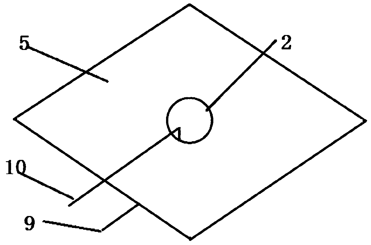
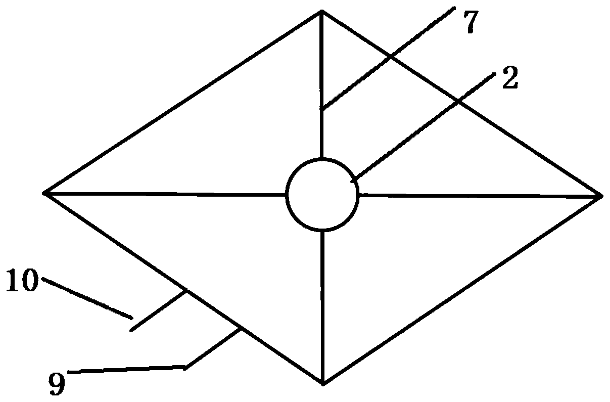
[0031] Example 1 as figure 2 , image 3 , Figure 4 As shown, a special-shaped photovoltaic cell structure includes a special-shaped photovoltaic cell structure body and positive and negative output. The special-shaped photovoltaic cell structure body includes a special-shaped structure sub-battery 1. through holes 2; special-shaped sub-batteries 1 are made of conventional battery chips or battery chips that do not meet the standard size, including crystalline silicon cells, thin-film cells, or flexible thin-film cells, etc., and then undergo mechanical stamping and mechanical cutting. Or cut and design the battery chip into the required special-shaped structure, such as triangle, prism, trapezoid, etc., by means of laser. The cutting process is a fine processing process to ensure that the positive and negative electrodes are disconnected, there is no short circuit and the battery is not broken under abnormal conditions. Such as figure 2 As shown, a hole is drilled in th...

Embodiment 2

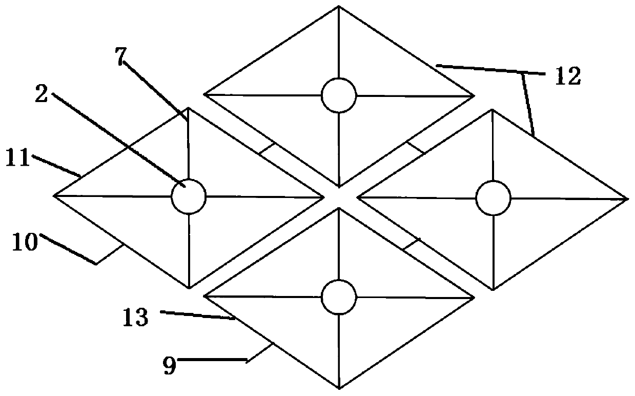
[0033] Example 2 as figure 1 , figure 2 , image 3 , Figure 4 The heterogeneous photovoltaic cell structure shown includes a plurality of heterogeneous structure subcells 1, the heterogeneous structure subcell 1 arranged at the first position is called the first heterogeneous structure subcell 11, and the heterogeneous structure subcell 1 arranged in the middle position is collectively referred to as It is the middle special-shaped structure sub-cell 12 , and multiple middle special-shaped structure sub-cells 12 can be selected and provided according to needs, and the terminal special-shaped structure sub-cell 13 is called the terminal special-shaped structure sub-cell 13 . On the heterogeneous structure sub-battery 1, there is provided a threading hole 2 that allows the current collection wire to pass through; Or flexible thin-film battery sheets, etc., and then cut and design the battery chips into required special-shaped structures, such as triangles, prisms, trapezoid...


PUM


Abstract

The invention belongs to the technical field of a photovoltaic cell and particularly relates to a shaped photovoltaic cell structure and a preparation method thereof. The shaped photovoltaic cell structure includes a shaped photovoltaic cell structure body and positive and negative output, wherein the shaped photovoltaic cell structure body includes shaped structure sub cells, threading holes forallowing current collecting wires to pass through are disposed on the shaped structure sub cells, the threading holes are internally filled with insulating glue for insulating the periphery of the threading holes, and insulating films for insulating a front electrode layer from a back electrode layer and insulating the back electrode layer from a bus bar connecting line are further arranged at thebottom of the back electrode layer. The shaped photovoltaic cell structure is advantaged in that the current of the overall shaped photovoltaic cell structure is no longer limited by the minimum current, the dead zone area of the battery is smaller, production positioning requirements are lower, and the product yield is higher.

Description

technical field [0001] The invention belongs to the technical field of photovoltaic cells, and in particular relates to a heterogeneous photovoltaic cell structure and a preparation method thereof. Background technique [0002] At present, photovoltaic cells are mainly based on standardized structures. Regardless of crystalline silicon cells, thin-film cells, and special cells, they are generally square and rectangular. The series-parallel connection of subsequent products is greatly restricted due to the layout structure limitations brought by the conventional shape. There is little reference to special-shaped products and their topological structures. Although a special-shaped battery is also disclosed in the Chinese invention patent, Patent No. 201310753801 for the production method of special-shaped thin-film photovoltaic modules, it is not actually a special-shaped battery in the true sense. Although it is called a special-shaped battery, its battery part is still rect...

Claims


Application Information

Patent Timeline
Patent Type & Authority Applications(China)
IPC IPC(8): H01L31/05H01L31/18
CPCH01L31/0508H01L31/1876Y02E10/50Y02P70/50
Inventor 陈国栋陈艳贞陈维强严军辉刘景涛苗卫民
Owner 西安富阎移动能源有限公司
Why Eureka
Try Eureka