Multi-frequency array antenna
An array antenna and antenna technology, which is applied in the directions of antenna, antenna coupling, antenna array, etc., can solve the problems of high cost, large cost and space occupied by operators, and large occupancy rate of 4G communication, etc., and achieve good electrical performance indicators and improved System isolation and effect of reducing coupling effects
- Summary
- Abstract
- Description
- Claims
- Application Information
AI Technical Summary
Problems solved by technology
Method used
Image
Examples
Embodiment 1
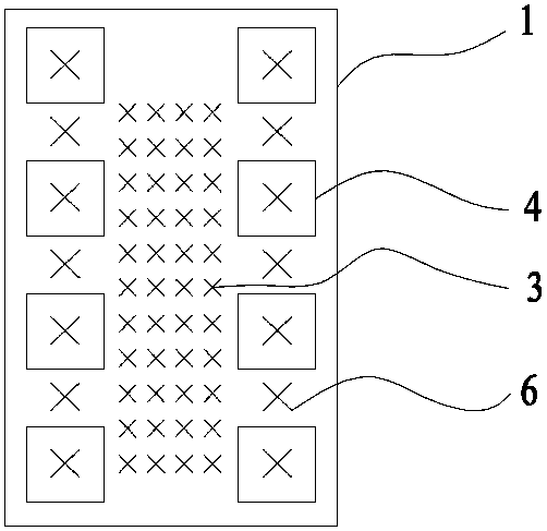
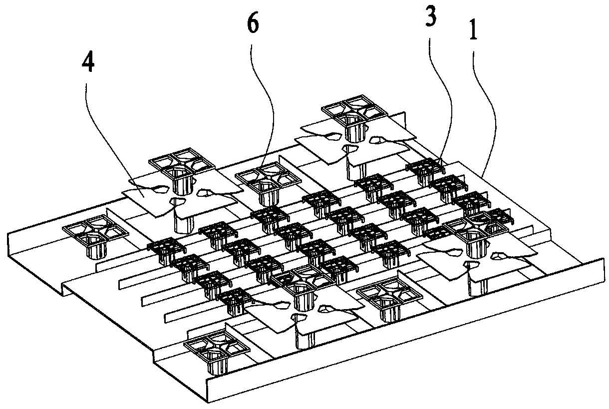
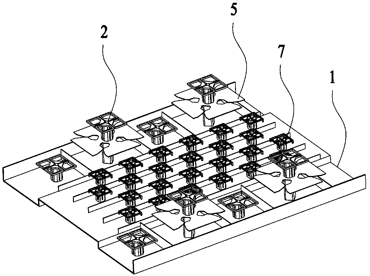
[0037] The multi-frequency array antenna in this embodiment includes a metal reflector 1, four rows of TDD antenna arrays 3 and two rows of FDD antenna low-frequency arrays 4 arranged above the reflector 1, and four rows of TDD antenna arrays 3 are arranged in parallel, and two rows of FDD antenna arrays are arranged in parallel. Antenna low-frequency arrays 4 are arranged symmetrically on the left and right sides of four columns of TDD antenna arrays 3, and each column of FDD antenna low-frequency arrays 4 is composed of several low-frequency radiation units b5, and each low-frequency radiation unit b5 is directly above and on both sides Each is provided with a high-frequency radiation unit a2, and multiple high-frequency radiation units a located on the same side form an FDD antenna high-frequency array 6; the high-frequency radiation unit a2 and the low-frequency radiation unit b5 are coaxially arranged, and two adjacent Only one high-frequency radiation unit a2 is arranged ...
Embodiment 2
[0043] The difference between this embodiment and Embodiment 1 is that the radiating elements c 7 included in any two adjacent columns of the TDD antenna array 3 are staggered, that is, the radiating elements c 7 are misplaced, which can effectively reduce the gap between the arrays. Inter-coupling effect, improve system isolation.
Embodiment 3
[0045] The difference between this embodiment and Embodiment 1 is that only one high-frequency radiation unit a2 is arranged directly above and on the front and rear sides of the low-frequency radiation unit b5 contained in one row of FDD antenna low-frequency array 4, and a plurality of radiation units located on the same side The high-frequency radiation unit a forms the FDD antenna high-frequency array 6; this embodiment is also an array formation method derived from the present invention, which reduces antenna costs while providing 4G and 5G network functions.
[0046] The multi-frequency array antenna of the present invention is composed of an FDD antenna and a TDD antenna. The low frequency band of the FDD antenna is 698MHz~960MHz or 617MHz~894MHz, and the high frequency band is 1427MHz~2690MHz or 1710MHz~2690MHz. The frequency band of the TDD antenna is divided into high and low frequency bands, supporting Dual frequency system, the low frequency range is 2490MHz ~ 2690M...
PUM
 Abstract
Description
Claims
Application Information
 - R&D
- Intellectual Property
- Life Sciences
- Materials
- Tech Scout
- Unparalleled Data Quality
- Higher Quality Content
- 60% Fewer Hallucinations
Browse by: Latest US Patents, China's latest patents, Technical Efficacy Thesaurus, Application Domain, Technology Topic, Popular Technical Reports.
© 2025 PatSnap. All rights reserved.Legal|Privacy policy|Modern Slavery Act Transparency Statement|Sitemap|About US| Contact US: help@patsnap.com


