Vector control position estimation compensation method based on Hall position sensor

A Hall position and compensation method technology, applied in the direction of torque ripple control, electronic commutator, etc., can solve problems such as installation accuracy errors, achieve compensation of installation position deviation, compensation of position angle distortion, reduction of torque ripple and noise effect

Active Publication Date: 2019-10-25
JIANGSU UNIV
View PDF6 Cites 21 Cited by
  • Summary
  • Abstract
  • Description
  • Claims
  • Application Information

AI Technical Summary

Problems solved by technology

[0021] Purpose of the invention: In order to solve the existing permanent magnet synchronous motor control, the position estimation algorithm is affected by the installation accuracy of the Hall position sensor and the symmetry of the magnetic pole of the rotor magnet. The permanent magnet synchronous motor position esti

Method used


Image

  • Vector control position estimation compensation method based on Hall position sensor
  • Vector control position estimation compensation method based on Hall position sensor
  • Vector control position estimation compensation method based on Hall position sensor

Examples


Embodiment example

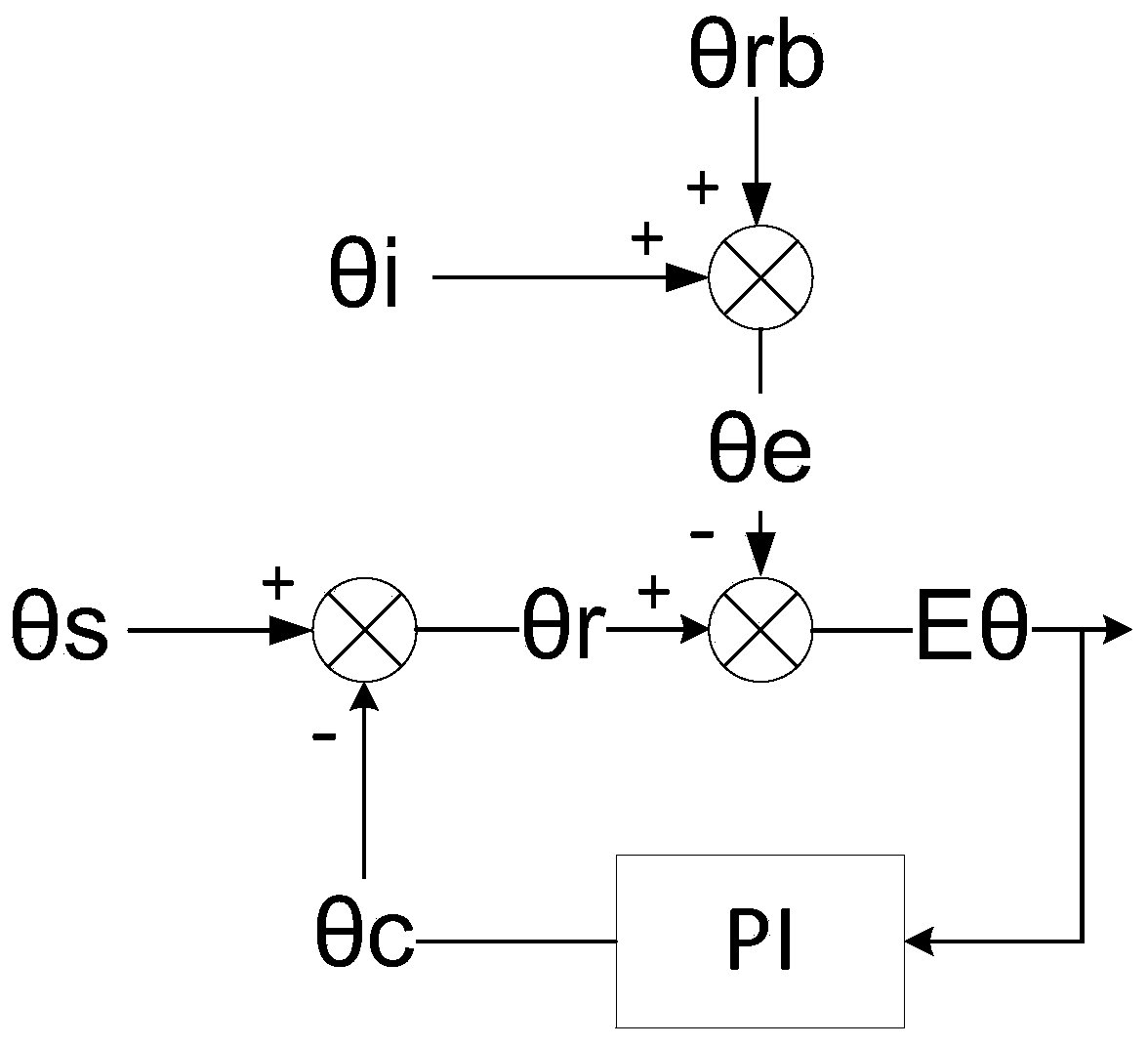
[0060] When the second jump edge is detected, according to the state change of the Hall sensor, it is judged that the motor is rotating forward, and the corresponding rotor angle θr=θs is 0°. Set the current position as the initial angle θrb of the first sector, and the initial angle is 0°. And the time interval between two jump edges is T, then when running in the first sector for t time, the estimated rotor angle θe=θrb+θi, that is, θe=0°+60*t / T.

[0061] When the third jump edge is detected, enter the second sector. According to the Hall state, the uncompensated installation angle θs=60° and the compensation value θc=0° of the second sector are obtained, then θr=θs-θc= 60°. And the total running time of the first sector is 0.9T, the estimated value of the initial angle of the second sector is θe=0°+60*0.9T / T=54°, then Eθ=θr-θe=6°. Assuming Ki=0.1, then θc=θc+Eθ*Ki=0.6°, then θs will also be used as the initial angle θb of the current sector at this time, that is, θb=60°. ...


PUM


Abstract

The invention discloses a position estimation compensation method for a permanent magnet synchronous motor based on a Hall position sensor, and the method comprises the following steps: carrying out the sector division of each electrical angle of an electrical angle period of a rotor in the permanent magnet synchronous motor, and obtaining an actual initial angle theta<rb> of a corresponding sector when a signal of the Hall position sensor jumps from an edge; estimating an angle increment theta in an interval according to the rotating speed of the permanent magnet synchronous motor; obtaining an estimated angle theta<e> according to a formula: theta<e>= theta<rb>+ theta; further calculating the actual installation angle theta<r> of the Hall position sensor; finally solving the difference between the estimated angle theta<e> and the actual installation angle theta<r> to obtain an error E<theta>, and calculating a compensation value theta<c> through a PI regulator, wherein after the process is circularly executed in this way for multiple periods, E<theta> approaches 0, and when motor control is conducted, three-phase sine voltage waveform distortion is greatly reduced, and torque pulsation and noise are reduced.

Description

Technical field: [0001] The invention belongs to the technical field of motor control, in particular to a method for estimating and compensating the position of a permanent magnet synchronous motor based on a Hall position sensor. Background technique: [0002] Commonly used rotor position sensors for permanent magnet synchronous motors include resolvers, quadrature encoders, and Hall position sensors. Among them, the resolver and quadrature encoder have the advantages of high precision, but need to install additional equipment on the motor; the Hall sensor can be directly installed inside the motor, which is simple and convenient, but the disadvantage is low precision. The three-phase position signal provided by the three-phase Hall position sensor is as follows: figure 1 As shown, when the rotor rotates at a constant speed, the Hall position sensor provides three square wave signals with a duty cycle of 50% and a phase difference of 120°. The rising and falling edges of ...

Claims


Application Information

Patent Timeline
IPC IPC(8): H02P6/16H02P6/10
CPCH02P6/10H02P6/16
Inventor 胡方圆沈跃何思伟
Owner JIANGSU UNIV
Why Eureka
Try Eureka