A digital to analog conversion circuit

A digital-to-analog conversion and circuit technology, applied in the electronic field, can solve the problems of large circuit area, circuit waste, and high circuit cost of digital-to-analog converters, and achieve the goal of fewer digital control digits, reduced circuit complexity, and reduced area cost Effect

Active Publication Date: 2022-05-13
SHANGHAI ANALOGY SEMICON TECH LTD
View PDF0 Cites 0 Cited by
  • Summary
  • Abstract
  • Description
  • Claims
  • Application Information

AI Technical Summary

Problems solved by technology

[0003] The existing digital-to-analog converter converts the input digital signal into an analog signal output by using the voltage division form of the analog signal. Common voltage dividers, such as resistor string voltage dividers and "R-2R" ladder resistive networks, are usually used for To improve the output accuracy of the digital-to-analog converter, the number of voltage-dividing resistors required increases exponentially with the input digital signal, so that the digital-to-analog converter requires a larger circuit area, and its circuit cost is too large
In addition, for some special applications, for example, the output voltage of the digital-to-analog converter only needs to have high precision near a certain common-mode voltage, and the use of the existing voltage division form will cause a large circuit waste

Method used


Image

  • A digital to analog conversion circuit
  • A digital to analog conversion circuit
  • A digital to analog conversion circuit

Examples


Embodiment 1

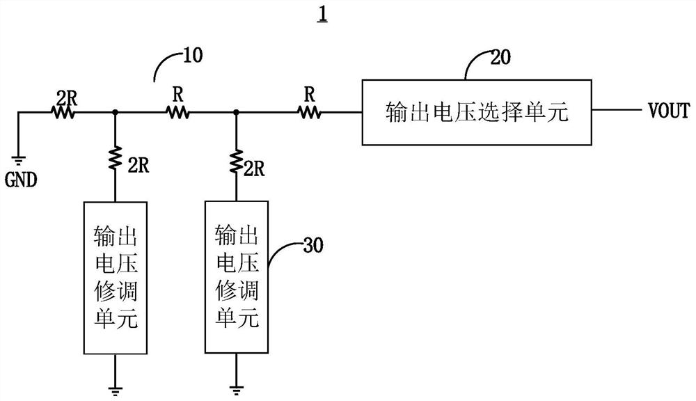
[0035] figure 1 A digital-to-analog conversion circuit 1 disclosed in an embodiment of the present application is shown, and the digital-to-analog conversion circuit 1 includes:

[0036] R-2R resistive network 10, the R-2R resistive network 10 is configured to be connected between the output terminal VOUT and the ground terminal GND;

[0037] an output voltage selection unit 20 configured to be connected between the output terminal of the R-2R resistive network 10 and the output terminal VOUT;

[0038] An output voltage trimming unit 30 configured to be connected between the 2R resistor on at least one branch of the R-2R resistive network 10 and the ground terminal GND.

[0039] In a preferred example, the output voltage selection unit 20 includes 2 parallel-connected n Each of the selection resistors is connected to a reference voltage or a ground terminal through a single-pole double-throw switch.

[0040] In a preferred example, the resistance value of the selection resi...

Embodiment 2

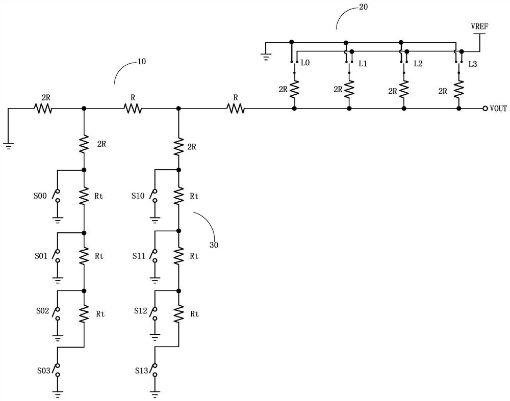
[0047] figure 2 A more detailed circuit diagram of the digital-to-analog conversion circuit in this embodiment is shown. The output voltage selection unit 20 includes 2 parallel-connectedn selection resistors, wherein n is 2, that is, 4 selection resistors are used to form 2 digital signal bits, and the resistance value of the selection resistors is 2R, and the selection resistors are respectively connected through single-pole double-throw switches L0, L1, L2, and L3 in turn Reference voltage VREF or ground terminal GND.

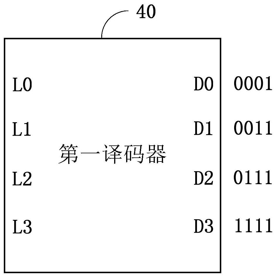
[0048] image 3 A schematic diagram of the first decoder 40 in an embodiment of the present application is shown. The first decoder 40 converts the input digital signals D0, D1, D2, D3 into control signals for the SPDT switches L0, L1, L2, L3 of the selection unit. If the digital signal of the switch state is "1", it means that one end of the connected selection resistor is connected to the reference voltage VREF, and the digital signal of the switch sta...

Embodiment 3

[0068] The multi-digit accurate output trimming DAC structure disclosed in the implementation of Embodiment 1 and Embodiment 2 performs trimming resistance control on the multi-order "R-2R" resistive network to achieve output voltage trimming accuracy and trim range. However, another embodiment of the present application also discloses a DAC structure for high-precision output voltage trimming, keeping the total number of digital control bits unchanged, and only performing multi-stage (partial branching) on ​​the "R-2R" resistive network. Road) expansion, can also achieve higher output voltage trimming accuracy.

[0069] refer to Image 6 As shown, the digital-to-analog conversion circuit includes: an R-2R resistive network 100, the R-2R resistive network 100 is configured to be connected between the output terminal VOUT and the ground terminal GND; an output voltage selection unit 200, the The output voltage selection unit 200 is configured to be connected between the outpu...


PUM


Abstract

The present application discloses a digital-to-analog conversion circuit, comprising: an R-2R resistive network configured to be connected between an output terminal and a ground terminal; an output voltage selection unit configured to be connected to the R-2R resistive network Between the output end of the network and the output end; an output voltage trimming unit, the output voltage trimming unit is set between the 2R resistor on at least one branch of the R-2R resistive network and the ground.

Description

technical field [0001] The present invention generally relates to the field of electronic technology, and in particular relates to a digital-to-analog conversion circuit. Background technique [0002] With the rapid development of computer technology, multimedia technology, and signal processing technology, advanced electronic systems continue to emerge, and digital-to-analog converters (Digital to analog converters, DACs) will be used in the front and back ends of modern advanced electronic systems. [0003] The existing digital-to-analog converter converts the input digital signal into an analog signal output by using the voltage division form of the analog signal. Common voltage dividers, such as resistor string voltage dividers and "R-2R" ladder resistive networks, are usually used for To improve the output precision of the digital-to-analog converter, the number of voltage dividing resistors required increases exponentially with the input digital signal, so that the dig...

Claims


Application Information

Patent Timeline
Patent Type & Authority Patents(China)
IPC IPC(8): H03M1/66H03M1/70H03M1/80
CPCH03M1/66H03M1/70H03M1/808H03M1/785H03M1/1057
Inventor 张俊张治安
Owner SHANGHAI ANALOGY SEMICON TECH LTD
Why Eureka
Try Eureka