
Powder liquid mixing and emulsifying machine and working method thereof

An emulsifying machine and powder-liquid technology, applied in the direction of mixing methods, mixers, chemical instruments and methods, etc., can solve the problems of uneven mixing of emulsifying machines, small application range of equipment, and poor emulsification effect, etc., to achieve convenient cleaning of equipment, High practicability and the effect of improving the effective contact surface

Pending Publication Date: 2019-10-29
太仓中新宝智能装备有限公司
View PDF0 Cites 2 Cited by
  • Summary
  • Abstract
  • Description
  • Claims
  • Application Information

AI Technical Summary

Problems solved by technology

[0005] 1. Most of the current emulsifiers have problems such as uneven mixing and poor emulsification effect, and the product quality is poor
[0006] 2. Most of the current emulsifiers can only process materials of a single nature, and the scope of application of the equipment is small and the practicability is poor.

Method used


Image

  • Powder liquid mixing and emulsifying machine and working method thereof
  • Powder liquid mixing and emulsifying machine and working method thereof
  • Powder liquid mixing and emulsifying machine and working method thereof

Examples


Embodiment 1

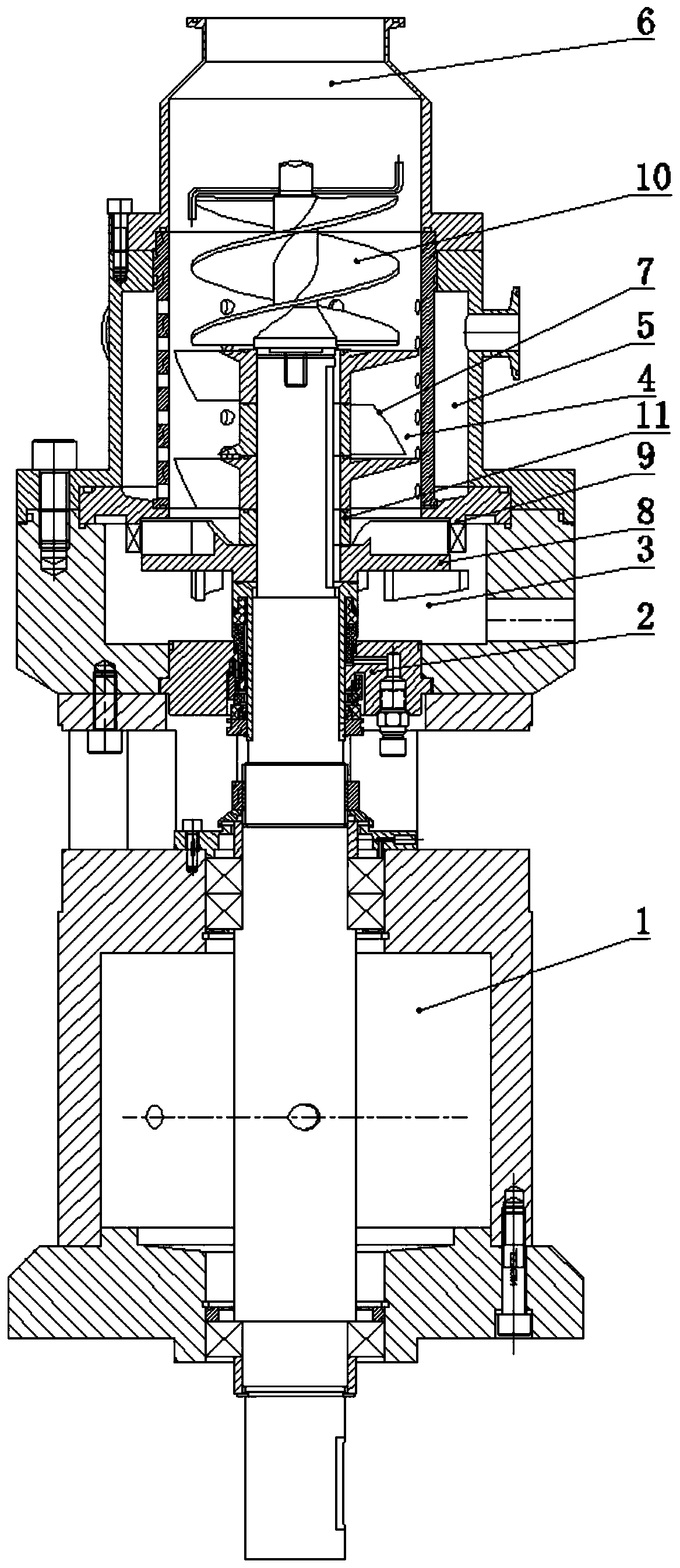
[0047] Such as Figure 1-8 A powder-liquid mixing and emulsifying machine is shown, comprising: a base body 1, a machine seal 2, a discharge cavity 3, a branch cylinder 4, a side material feeding cavity 5 and a top feeding cavity 6, wherein the base body 1 is provided with a main shaft , The outer side of the main shaft is provided with an organic seal 2, a shunt cylinder 4, and a top feed cavity 6 in sequence, the mechanical seal 2 is provided on the top of the base 1, and the outer side of the mechanical seal 2 is provided with a discharge cavity 3, the discharge cavity 3 is connected to the split tube 4, a side material feeding cavity 5 is provided outside the split tube 4, the side material feeding cavity 5 is in communication with the split tube 4, and the top of the split tube 4 is in communication with the top feeding cavity 6.

[0048] The shunt cylinder 4 described in this embodiment is provided with an impeller 7, a rotor 8 and a stator 9, and a rotor 8 is provided in th...

Embodiment 3

[0062] Such as figure 1 with 8 A powder-liquid mixing and emulsifying machine is shown, comprising: a base body 1, a machine seal 2, a discharge cavity 3, a branch cylinder 4, a side material feeding cavity 5 and a top feeding cavity 6, wherein the base body 1 is provided with a main shaft , The outer side of the main shaft is provided with an organic seal 2, a shunt cylinder 4, and a top feed cavity 6 in sequence, the mechanical seal 2 is provided on the top of the base 1, and the outer side of the mechanical seal 2 is provided with a discharge cavity 3, the discharge cavity 3 is connected to the split tube 4, a side material feeding cavity 5 is provided outside the split tube 4, the side material feeding cavity 5 is in communication with the split tube 4, and the top of the split tube 4 is in communication with the top feeding cavity 6.

[0063] The mechanical seal 2 described in this embodiment includes an inner mechanical seal body 21, a first moving ring 22, a first static ri...


PUM


Abstract

The invention discloses a powder liquid mixing and emulsifying machine. The powder liquid mixing and emulsifying machine comprises a matrix, a mechanical seal, a discharging chamber, a distributing cylinder, a side material feeding chamber and a top feeding chamber, a main shaft is arranged in the matrix, the mechanical seal, the distributing cylinder and the top feeding chamber are sequentially arranged on the outer side of the main shaft, the mechanical seal is arranged at the top of the matrix, the outer side of the mechanical seal is provided with the discharging chamber, the discharging chamber is connected with the distributing cylinder, the outer side of the distributing cylinder is provided with the side material feeding chamber, the side material feeding chamber communicates withthe distributing cylinder, and the top of the distributing cylinder communicates with the top feeding chamber; the distributing cylinder is internally provided with an impeller, a rotor and a stator;and a screw feeding block is arranged at the top of the main shaft. The invention further discloses a working method of the powder liquid mixing and emulsifying machine. According to the powder liquidmixing and emulsifying machine, a variety of inlets are formed, the feeding speed and stability can be controlled through spiral feeding, the effective contact surface of liquid materials is improvedthrough circumferential spraying, the mixing uniformity is improved through multi-layer impeller stirring, the material reaction is good, and the product quality is good.

Description

Technical field [0001] The invention belongs to the field of fine material processing, and particularly relates to a powder-liquid mixing emulsifier and a working method thereof. Background technique [0002] The mixing emulsifier is a high-performance equipment for continuous production or circulating processing of fine materials. In a narrow space cavity, an emulsifying device for emulsifying the material is installed. The mixing and emulsifying device can mix and disperse the material in the shortest time , Shearing, emulsification treatment, the particle size distribution range is also significantly narrowed. Thus, fine long-term stable products can be produced. [0003] Emulsifiers have a long history of development, but with the development of industrial technology and the increase in product demand, current emulsifiers still have many shortcomings. For example, current emulsifiers usually have problems such as uneven mixing and poor emulsification effect. At the same time,...

Claims


Application Information

Patent Timeline
Patent Type & Authority Applications(China)
IPC IPC(8): B01F3/08B01F13/10B01F15/00B01F15/02
CPCB01F23/4105B01F23/43B01F33/822B01F33/86B01F2035/3513B01F35/7179
Inventor 袁天刚刘友琴
Owner 太仓中新宝智能装备有限公司
Learn More