Leakage restoring device

A gas, gas-liquid separation technology, applied in the direction of fuel air filter, fuel air intake, engine components, etc., can solve the problems of increasing the number of parts and complexity

Inactive Publication Date: 2003-03-26
HONDA MOTOR CO LTD
View PDF2 Cites 0 Cited by
  • Summary
  • Abstract
  • Description
  • Claims
  • Application Information

AI Technical Summary

Problems solved by technology

[0003] However, even if the reduction chamber and the air cleaner case are integrally formed as described above, the reduction passage piping and the exhaust piping are required, and since the piping structure is relatively complicated, it is desirable to simplify the piping structure.
In addition, in order not to cause it to adhere to the filter and cause clogging, it is desirable to supply the blow-by air as close to the inlet of the connecting pipe as possible; however, for this purpose, the above-mentioned guide pipe, etc. are required, which increases the number of parts

Method used


Image

  • Leakage restoring device
  • Leakage restoring device
  • Leakage restoring device

Examples


Embodiment Construction

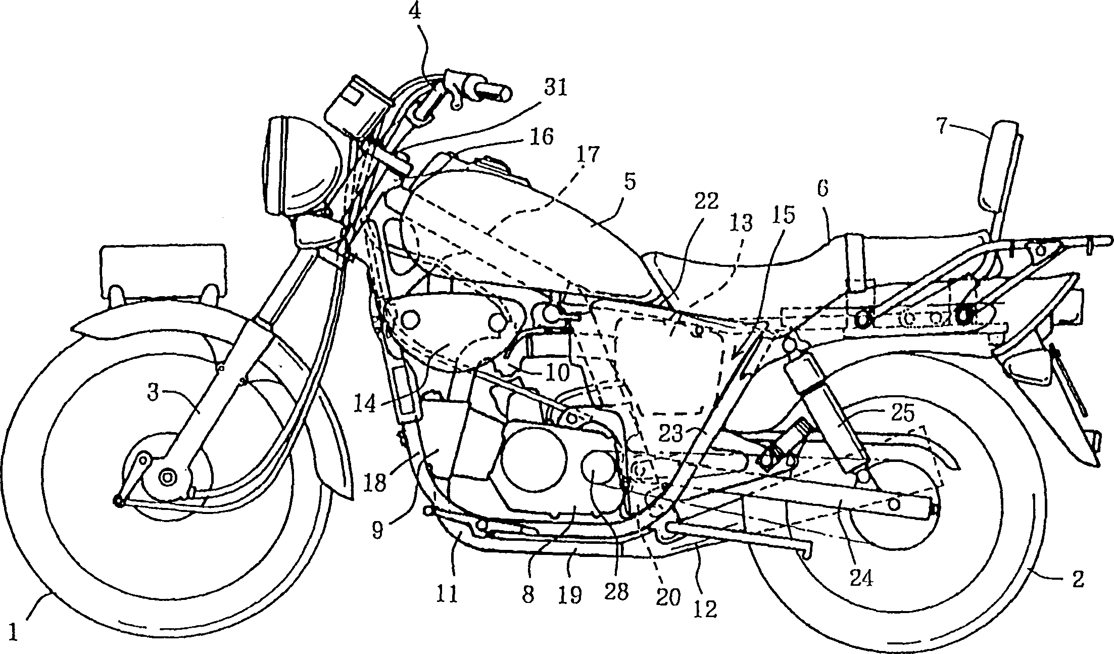
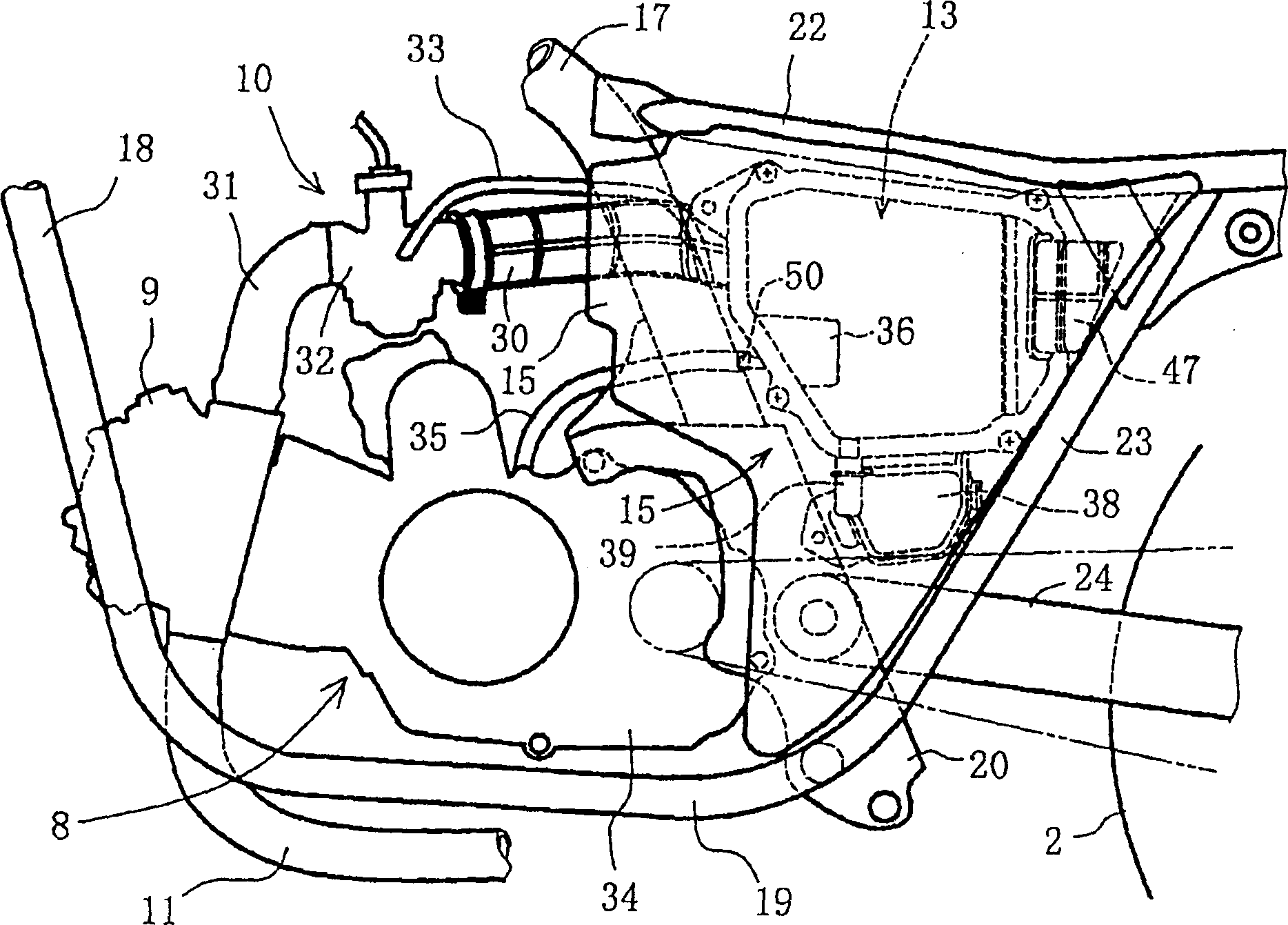
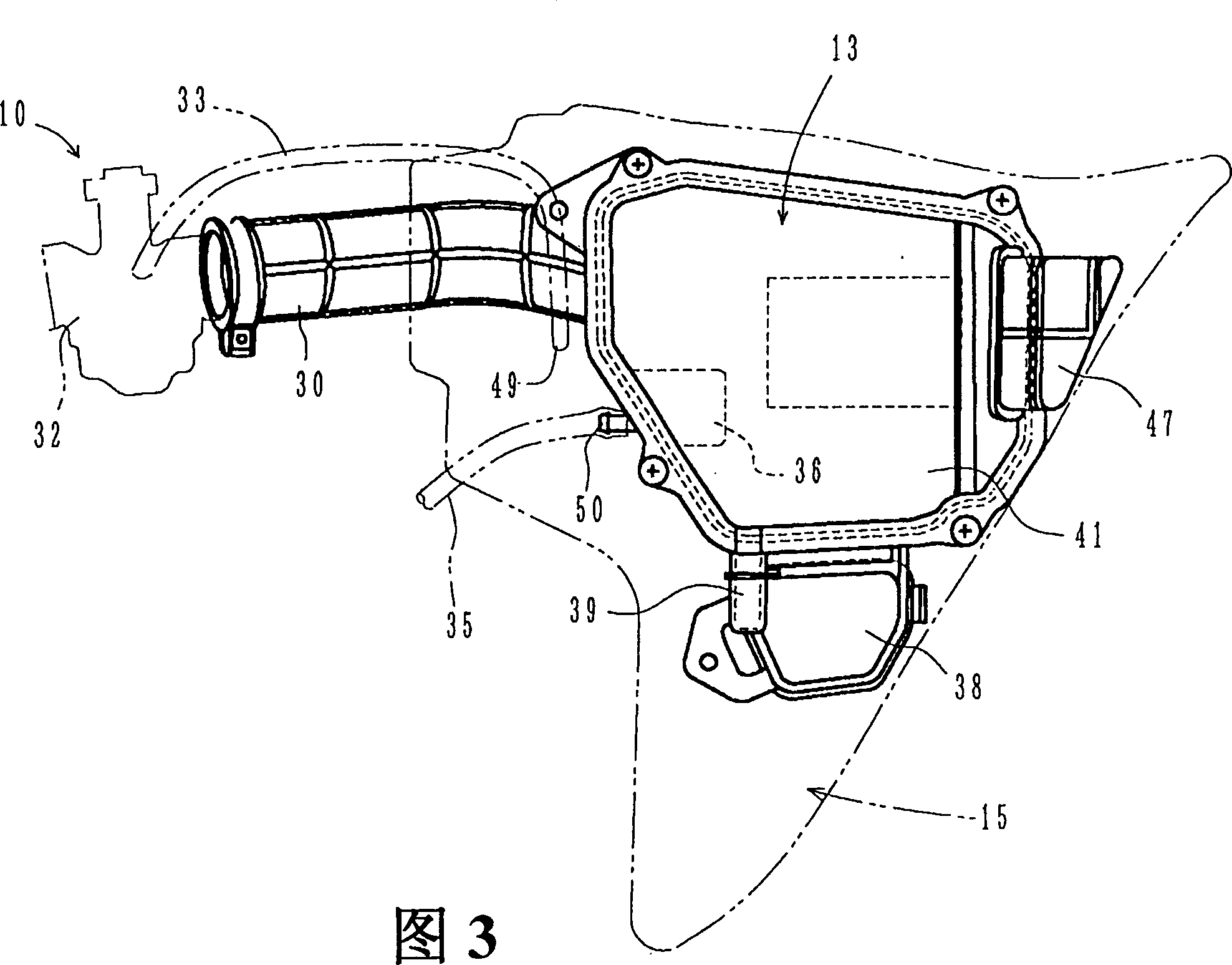
[0014] An embodiment of the present invention applicable to a two-wheeled motor vehicle will be described with reference to the drawings. figure 1 It is a left side view showing the direction of travel of the appearance of the two-wheeled motor vehicle; figure 2 It is an enlarged view showing the main parts around the engine; Fig. 3 is a further enlarged side view showing the housing part of the air filter; Fig. 4 is a cross-sectional view thereof; Figure 5 It is a side view of the housing body part showing its interior with the cover removed; Image 6 It is a partially enlarged view showing a part of the reduction chamber cut away.

[0015] First, the overall structure of this two-wheeled motor vehicle will be schematically described. Such as figure 1 As shown, the two-wheeled motor vehicle is an American structure, and it has the following characteristics: a front wheel 1 and a rear wheel 2 forming a long track, a front fork 3 with a large caster angle of the steering w...


PUM


Abstract

A return passage extending from the breather chamber of an engine is connected at one end to a joint part at the lower end of a return chamber. The return chamber is integrated with the interior of a clean side in an air cleaner case body so as to connect to the clean side via a communication hole formed in the top of a return chamber cover. An inflected passage including ribs is defined between the joint part and the communication hole to offer a vapor-liquid separation section where blowby gas is filtered to give gas contents, which is fed into the clean side via the communication hole, and water contents, which is urged to flow back into the joint part or into the return passage that returns it to the crankcase breather chamber. This system requires no drain lines and only simple pipe arrangement to thus reduce the number of components used.

Description

technical field [0001] The invention relates to a blow-by gas reducing device for an internal combustion engine such as a two-wheeled motor vehicle. Background technique [0002] In Japanese Shigong Zhao No. 56-24258, such an air leakage reduction device is shown: a long channel-shaped air leakage reduction chamber is integrally formed from the top wall of the air filter housing along the back wall; the upper end of the reduction chamber is passed through the pipeline The reduction path of the engine is connected to the blow-by part of the engine, and its lower end is connected to the exhaust pipe. The leakage air introduced into the device is separated by gas and liquid while flowing from the upper part to the lower part, and the gas component is supplied to the vicinity of the inlet of the connecting pipe through the guide pipe installed on the inner side of the top wall of the air filter housing, together with the clean air in the clean side. into the vaporizer. [0003...

Claims


Application Information

Patent Timeline
Patent Type & Authority Patents(China)
IPC IPC(8): F01M13/00F02B61/06F02M35/10
CPCF02B61/06
Inventor 荻巢纪之松浦弘明
Owner HONDA MOTOR CO LTD
Why Eureka
Try Eureka