Micro acoustic sensor based on diffraction grating structure

An acoustic sensor and diffraction grating technology, which is applied to instruments, utilizes wave/particle radiation, and measures ultrasonic/sonic/infrasonic waves, etc. It can solve the problems of low signal-to-noise ratio and high noise of MEMS acoustic sensors, and achieve low cost and increased perforation rate, reducing the effect of damping

Inactive Publication Date: 2019-10-29
SHANDONG UNIV
View PDF6 Cites 5 Cited by
  • Summary
  • Abstract
  • Description
  • Claims
  • Application Information

AI Technical Summary

Problems solved by technology

The technical solution provided by the invention solves the problems of high noise and low signal-to-noise ratio of...

Method used


Image

  • Micro acoustic sensor based on diffraction grating structure
  • Micro acoustic sensor based on diffraction grating structure
  • Micro acoustic sensor based on diffraction grating structure

Examples


Embodiment 1

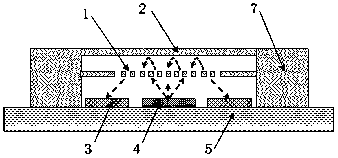
[0038] A miniature acoustic sensor based on a diffraction grating structure, such as figure 1As shown, it includes MEMS chip, VCSEL4, PD3 and substrate 5; both VCSEL4 and PD3 are fixedly installed on substrate 5, VCSEL4 is located in the center of substrate 5, PD3 is distributed on both sides of VCSEL4, and the distance d between PD3 and VCSEL4 is not less than 10μm;

[0039] The MEMS chip, VCSEL4 and PD3 are located in a closed cavity. The MEMS chip includes a diffraction grating 1 and a thin film mirror 2. The thin film mirror 2 is located above the diffraction grating 1. An upper cavity is formed between the thin film mirror 2 and the diffraction grating 1. The diffraction grating A lower cavity is formed between the grating 1 and the substrate 5; the distance h between the thin film mirror 2 and the diffraction grating 1 is 0.5-4 μm.

[0040] In the micro-acoustic sensor, an upper cavity is formed between the thin film mirror 2 and the diffraction grating 1, and the sound...

Embodiment 2

[0053] A kind of microacoustic sensor based on the diffraction grating structure provided according to embodiment 1, its difference is:

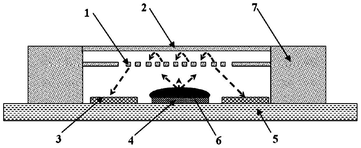
[0054] Such as figure 2 As shown, a collimating lens 6 is installed on the VCSEL4. The function of the collimating lens 6 is to collimate the light spot emitted by the VCSEL4, increase the light intensity of the + / - 1st order diffracted light of the diffraction grating to the PD3, and improve the sensitivity of the sensor. figure 2 The direction of the arrow in the middle is the path that the light passes through.

Embodiment 3

[0056] A kind of microacoustic sensor based on the diffraction grating structure provided according to embodiment 1, its difference is:

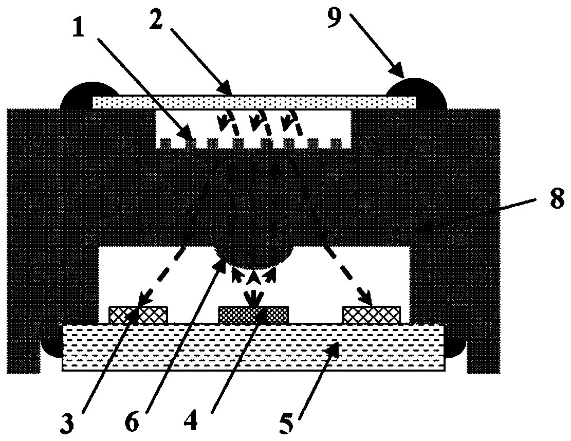
[0057] Such as image 3 As shown, an optical collimator structure 8 is arranged between the substrate 5 and the MEMS chip, the upper part of the optical collimator structure 8 is an upper groove structure, the lower part of the optical collimator structure 8 is a lower groove structure, and the diffraction grating in the MEMS chip 1 is arranged on the groove bottom surface of the upper groove, and the film reflector 2 is connected to the upper edge of the optical collimator structure 8 through the fixing glue 9, and the film reflector 2 forms an upper cavity for light reflection with the grating and the upper groove. The lower groove is connected to the substrate 5 through a fixing glue 9; the groove bottom of the lower groove is an inverted collimator lens 6, and the inverted collimator lens 6 is located directly above the VCSEL4. When the...


PUM

PropertyMeasurementUnit
Thicknessaaaaaaaaaa
Thicknessaaaaaaaaaa

Abstract

The invention relates to a micro acoustic sensor based on a diffraction grating structure. The micro acoustic sensor comprises a MEMS chip, a VCSEL, a PD and a substrate, wherein the MEMS chip comprises a diffraction grating and a membrane mirror; the membrane mirror is located above the diffraction grating; an upper cavity is formed between the membrane mirror and the diffraction grating; and a lower cavity is formed between the diffraction grating and the substrate. The micro acoustic sensor, based on an optical principle, improves a capacitive sensor structure, optimizes the size and the structure of the diffraction grating, adjusts the distance between the diffraction grating and a thin film sensor, converts an acoustic signal into a light intensity change signal, and further convertsthe light intensity change signal into an electric signal to be output by an photoelectric detector. The diffraction grating reduces the noise of the structure. The optical principle improves the sensitivity of the sensor, solves the low sensitivity and large noise of a current MEMS acoustic sensor, and has the advantages of flexible structure design and low cost.

Description

technical field [0001] The invention relates to a micro-acoustic sensor based on a diffraction grating structure, belonging to the technical field of micro-acoustic sensors. Background technique [0002] An acoustic sensor is an electronic device that converts sound vibration signals into electrical signals. The development of modern measurement technology has higher and higher requirements for parameters such as sensor size, receiving sensitivity, and signal-to-noise ratio. At present, the mainstream miniature acoustic sensors have two solutions: MEMS piezoelectric sensors and MEMS capacitive sensors. [0003] The MEMS piezoelectric sensor mainly uses the vibration signal to deform the piezoelectric transducer, causing the redistribution of charges on the two poles of the transducer, and then converting it into an electrical signal output. Piezoelectric sensors have disadvantages such as poor anti-interference ability, small output energy, poor sensing frequency character...

Claims


Application Information

Patent Timeline
IPC IPC(8): G01H9/00
CPCG01H9/00
Inventor 陶继方肖世瑾李炎赵佳
Owner SHANDONG UNIV
Why Eureka
Try Eureka