An insulation drip tube and its purpose

A technology for drip tubes and uses, applied in the field of insulating drip tubes, to achieve the effect of no moving parts, no drive, and no control loop

Active Publication Date: 2022-08-09
江南山
View PDF3 Cites 0 Cited by
  • Summary
  • Abstract
  • Description
  • Claims
  • Application Information

AI Technical Summary

Problems solved by technology

[0004] Based on the technical bottlenecks existing in existing flow batteries, semi-flow batteries, fuel cells and some industrial devices involving continuous delivery of conductive liquids, the present invention provides an insulating drip tube to solve the problem of battery cell electrodes and supply, Electrical insulation between return pipes and various conductive liquid continuous conveying devices

Method used


Image

  • An insulation drip tube and its purpose
  • An insulation drip tube and its purpose
  • An insulation drip tube and its purpose

Examples


Embodiment 1

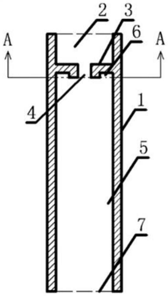
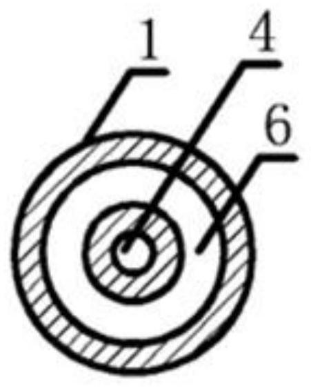
[0030] like figure 2 , 3 As shown, an insulating drip tube includes a tube body 1, and the tube body 1 is provided with a liquid inlet 2, a diaphragm 3, a lumen 5 and a liquid outlet 7 in sequence from top to bottom; the The diaphragm 3 is sealingly connected with the tube wall of the pipe body 1, and a drip hole 4 is arranged in the middle of the diaphragm 3, and the drip hole 4 communicates the liquid inlet 2 and the lumen 5. The outer circumference of the drip hole 4 A groove 6 is provided between the inner wall surface of the lumen 5 . The lumen 5 is filled with inert gas; the wall of the lumen 5 is made of insulating material.

[0031] In a further solution, the inner wall surface of the lumen 5 is coated with polytetrafluoroethylene. The inert gas includes nitrogen gas and argon gas, and the insulating material includes glass material, ceramic material, and polymer material.

[0032] In a further solution, the cross-sectional shape of the pipe body 1 is circular.

...

Embodiment 2

[0036] like Figure 4 , 5 As shown, an insulating drip tube includes a tube body 1, and the tube body 1 is provided with a liquid inlet 2, a diaphragm 3, a lumen 5 and a liquid outlet 7 in sequence from top to bottom; the The diaphragm 3 is sealingly connected with the tube wall of the pipe body 1, and four drip holes 4 are arranged in the middle of the diaphragm 3, and the four drip holes 4 are arranged in an array to form a drip hole array. A groove 6 is provided between the inner wall surfaces of the cavity 5 . The drip hole 4 communicates the liquid inlet 2 and the lumen 5; the lumen 5 is filled with inert gas; the cavity wall of the lumen 5 is made of insulating material.

[0037] In a further solution, the inner wall surface of the lumen 5 is coated with polytetrafluoroethylene.

[0038] In a further solution, the cross-sectional shape of the pipe body 1 is circular.

[0039]When the conductive liquid flows to the four drop holes 4 through the liquid inlet 2, nearly ...

Embodiment 3

[0042] like Image 6 , 7 As shown, an insulating drip tube includes a tube body 1, and the tube body 1 is provided with a liquid inlet 2, a diaphragm 3, a lumen 5 and a liquid outlet 7 in sequence from top to bottom; the The diaphragm 3 is sealingly connected with the tube wall of the pipe body 1, and a drip hole 4 is arranged in the middle of the diaphragm 3, and the drip hole 4 communicates the liquid inlet 2 and the lumen 5, and the lumen 5 is filled with water. There is an inert gas; the wall of the lumen 5 is made of insulating material.

[0043] In a further solution, the inner wall surface of the lumen 5 is coated with polytetrafluoroethylene.

[0044] A further scheme, a further scheme, the cross-sectional shape of the pipe body 1 is a rectangle, such as Image 6 , 7 As shown, the tube body 1 located on the two short sides of the rectangle is each provided with a groove 6, and the groove 6 is located between the outer circumference of the drip hole 4 and the inner ...


PUM


Abstract

The invention provides an insulating drip tube and its use. An insulating drip tube includes a tube body, and the tube body is provided with a liquid inlet, a diaphragm, a lumen and a liquid outlet in sequence from top to bottom. The diaphragm is sealed with the pipe wall of the pipe body, and one or more drip holes are arranged in the middle of the diaphragm, and the drip holes connect the liquid inlet and the lumen; There is an inert gas; the wall of the lumen is made of insulating material. The device can change the continuous flowing conductive liquid into discontinuous and mutually insulating droplets in the device, and maintain the electrical insulation of various conductive liquid conveying processes under the premise of ensuring the uniform flow of the conductive liquid, and has a small volume and no moving parts. , no drive, no control loop, simple structure, reliable performance, easy to integrate with equipment.

Description

technical field [0001] The invention relates to a conveying device, in particular to an insulating drip tube and its application. Background technique [0002] Since the beginning of the 21st century, with the increasing demand for energy from human activities, energy crisis and environmental problems have become two major focuses of global attention. In order to meet the needs of electric vehicles and large-scale energy storage power stations, countries around the world are actively carrying out innovative research in the field of power storage batteries. For example, liquid metal fuel cells and flow batteries are a new type of power storage battery with high power density, high energy density, high safety and low cost. The basic structural principles are as follows: figure 1 As shown, the cathode feed pipe 11 feeds the cathode active material into the cathode, and the reacted cathode residue is returned to the cathode return pipe 12; the anode feed pipe 13 feeds the anode...

Claims


Application Information

Patent Timeline
Patent Type & Authority Patents(China)
IPC IPC(8): H01M8/04082H01M8/04186
CPCH01M8/04186H01M8/04201Y02E60/50
Inventor 江南山
Owner 江南山
Why Eureka
Try Eureka