
Low-temperature flue gas ozone denitration system

A low-temperature flue gas and ozone technology, applied in the field of flue gas denitrification, can solve the problems of large floor area, human health hazards, and high equipment investment, and achieve the effect of small investment, small floor area, and high processing efficiency

Pending Publication Date: 2019-11-01
广州格邦机械工程有限公司
View PDF5 Cites 1 Cited by
  • Summary
  • Abstract
  • Description
  • Claims
  • Application Information

AI Technical Summary

Problems solved by technology

[0002] The variety of heat treatment process types and the shape and size of the heat treatment workpiece, the heat treatment furnace furnace type and structure are also various. The heat treatment furnace refers to the electric furnace or fuel furnace used for heat treatment and heating of the charge. A large amount of pollutants will be avoided, and air pollutants will harm human health: polluted air has a direct impact on human health; factories have not only concentration requirements for nitrate emissions, but also total requirements. The traditional denitrification system has the disadvantages of high equipment investment and large floor area. In addition to denitrification, it can also remove other harmful gases in the flue gas, such as sulfur, mercury and other substances. Ozone oxidation with a small footprint Low temperature and low concentration flue gas denitrification system is very important

Method used


Image

  • Low-temperature flue gas ozone denitration system
  • Low-temperature flue gas ozone denitration system
  • Low-temperature flue gas ozone denitration system

Examples


Embodiment Construction

[0032] The following will clearly and completely describe the technical solutions in the embodiments of the present invention with reference to the accompanying drawings in the embodiments of the present invention. Obviously, the described embodiments are only some, not all, embodiments of the present invention.

[0033] In describing the present invention, it should be understood that the terms "upper", "lower", "front", "rear", "left", "right", "top", "bottom", "inner", " The orientation or positional relationship indicated by "outside", etc. is based on the orientation or positional relationship shown in the drawings, and is only for the convenience of describing the present invention and simplifying the description, rather than indicating or implying that the referred device or element must have a specific orientation, so as to Specific orientation configurations and operations, therefore, are not to be construed as limitations on the invention.

[0034] refer to Figure ...


PUM


Abstract

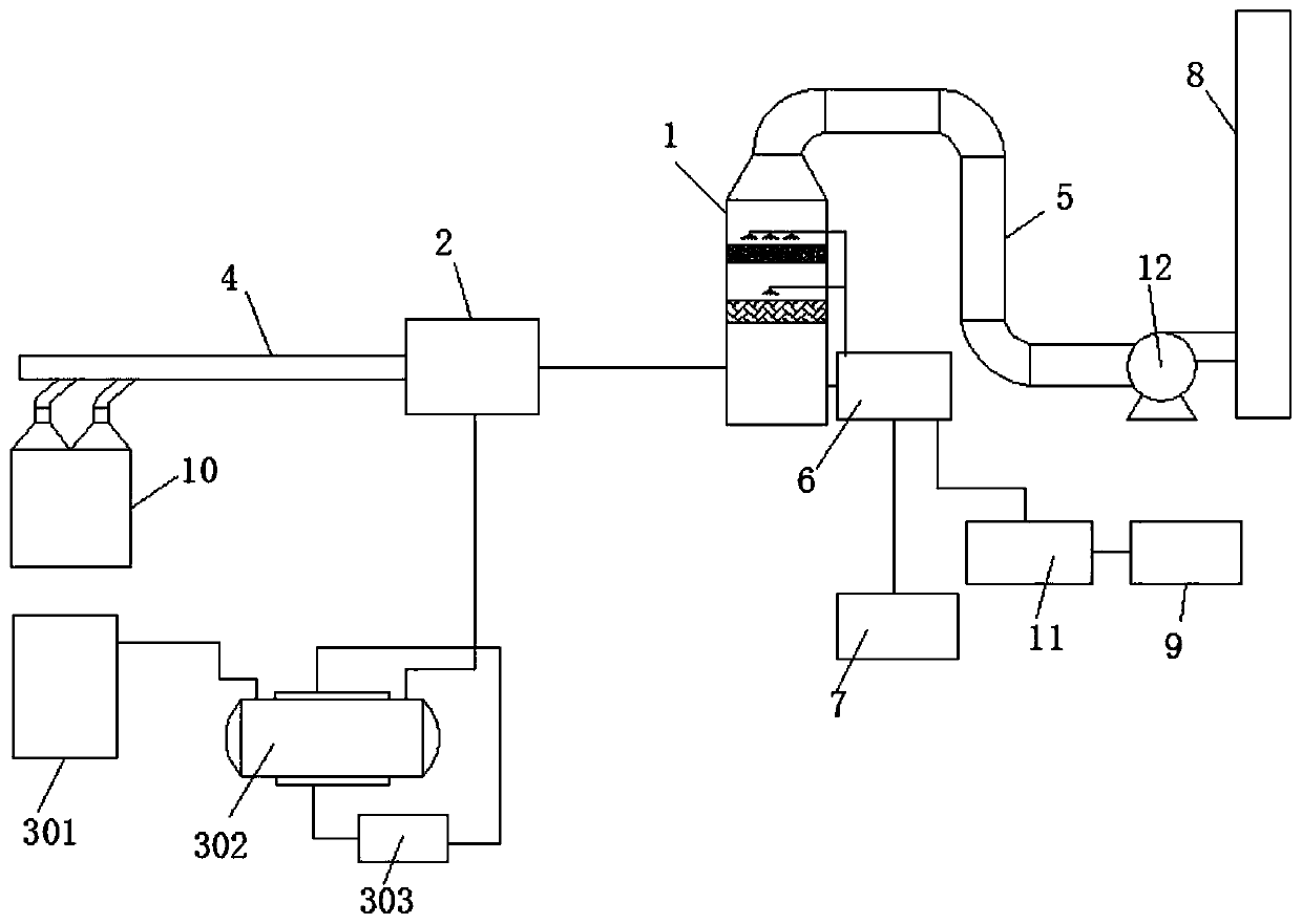
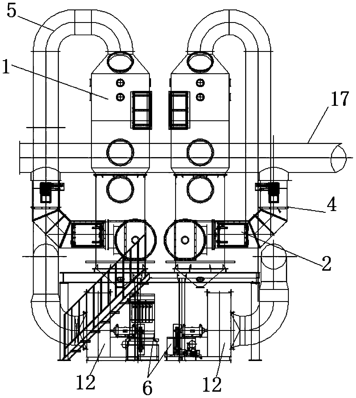
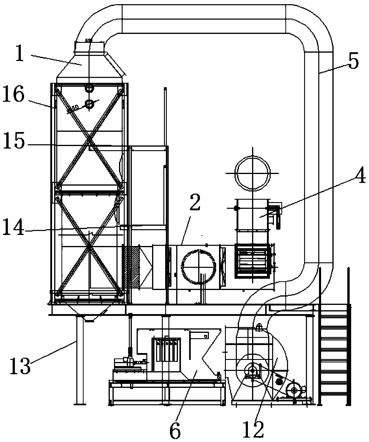
The invention discloses a low-temperature flue gas ozone denitration system, and belongs to the field of flue gas denitration. The low-temperature flue gas ozone denitration system comprises a spray purification tower; an ozone feeding and mixing device is connected to an inlet of the spray purification tower; an ozone device of which the output end is connected with the ozone feeding and mixing device; a waste gas inlet pipe connected with the ozone feeding and mixing device; an air outlet pipe connected to the upper end of the spray purification tower; a circulating water tank, of which thewater outlet end is connected with the spray pipe in the spray purification tower and the water inlet end is connected to the lower end of the spray purification tower. The waste gas inlet pipe is connected to a smoke outlet of the heat treatment furnace for cooling the flue gas to below 80 DEG C and feeding the flue gas into the ozone feeding and mixing device; meanwhile, ozone is generated through the ozone device, is conveyed into the ozone feeding and mixing device and is absorbed by an alkaline solution through the spraying purification tower, so that denitration is achieved. The system is small in occupied area, small in investment and high in low-concentration nitrogen oxide treatment efficiency.

Description

technical field [0001] The invention relates to the technical field of flue gas denitrification, in particular to a low-temperature flue gas ozone denitrification system. Background technique [0002] The variety of heat treatment process types and the shape and size of the heat treatment workpiece, the heat treatment furnace furnace type and structure are also various. The heat treatment furnace refers to the electric furnace or fuel furnace used for heat treatment and heating of the charge. A large amount of pollutants will be avoided, and air pollutants will harm human health: polluted air has a direct impact on human health; factories have not only concentration requirements for nitrate emissions, but also total requirements. The traditional denitrification system has the disadvantages of high equipment investment and large floor area. In addition to denitrification, it can also remove other harmful gases in the flue gas, such as sulfur, mercury and other substances. Ozo...

Claims


Application Information

Patent Timeline
Patent Type & Authority Applications(China)
IPC IPC(8): B01D53/75B01D53/76B01D53/78B01D53/48B01D53/56F27D17/00
CPCB01D53/75B01D53/76B01D53/78B01D53/56B01D53/48F27D17/008F27D17/00B01D2251/104B01D2251/304B01D2251/604B01D2258/0283B01D2257/602B01D2257/30Y02P10/25
Inventor 谭文俭
Owner 广州格邦机械工程有限公司
Learn More