Plate punching device for furniture production

A punching device and plate technology, applied in positioning devices, manufacturing tools, boring/drilling, etc., can solve the problems of reduced work efficiency, slow clamping speed, cumbersome operation, etc., to reduce clamping time, clamping Stabilize and improve work efficiency

Active Publication Date: 2019-11-01
GANZHOU WENHUA JIARUI FURNITURE IND CO LTD
View PDF8 Cites 17 Cited by
  • Summary
  • Abstract
  • Description
  • Claims
  • Application Information

AI Technical Summary

Problems solved by technology

[0004] However, the above-mentioned boards are installed with multiple fastening screws, and at least two people are required

Method used


Image

  • Plate punching device for furniture production
  • Plate punching device for furniture production
  • Plate punching device for furniture production

Examples


Example Embodiment

[0026] Example 1

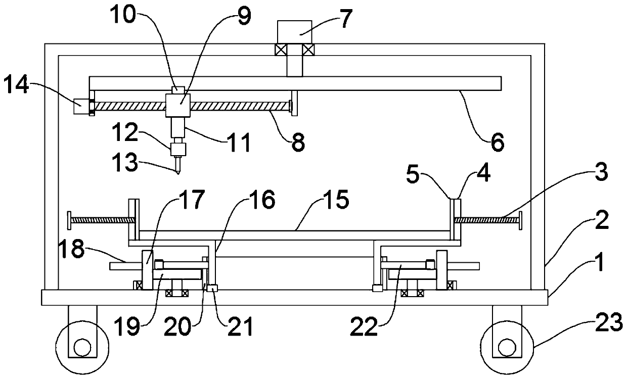
[0027] see Figure 1~3 , in an embodiment of the present invention, a board punching device for furniture production, including a workbench 1, a clamping mechanism and a punching mechanism, the upper surface of the workbench 1 is equipped with a clamping mechanism for fast clamping board 4 materials, A punching mechanism is arranged above the clamping mechanism. Supporting legs are installed on the four corners of the bottom of the workbench 1, and rollers 23 are installed at the bottom of the supporting legs. The rollers 23 are self-locking rollers to facilitate the movement of the device. The clamping mechanism includes a plurality of splints 4 arranged circumferentially around the sheet body 15 and a driving assembly for driving the plurality of splints 4 to move synchronously to the sheet body 15 and clamp them. Anti-slip protrusions are provided on each of the plurality of splints 4 In this embodiment, the number of splints 4 is preferably four and dis...

Example Embodiment

[0030] Example 2

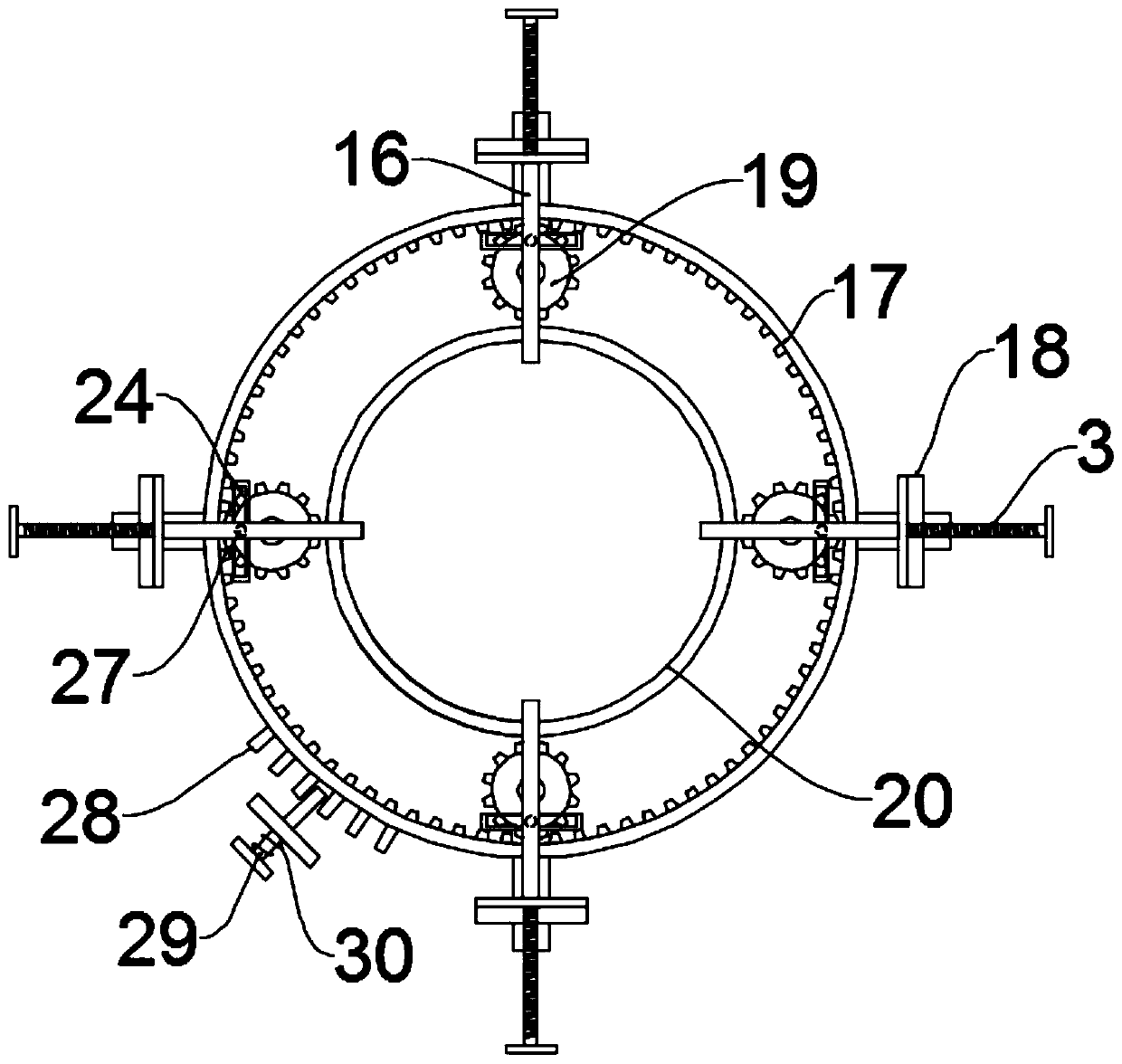
[0031] see Figure 4 The difference between the embodiment of the present invention and the embodiment is that, in order to avoid the dust generated during drilling from affecting the health of the workers, a suction nozzle 25 is installed on the mounting block 9 through a mounting rod, and the suction nozzle 25 is located at the drill bit 13 On the side, the suction nozzle 25 is connected with a trachea, and the other end of the trachea is connected with the vacuum cleaner 26, through which the dust generated is sucked in, so as to avoid flying around and affecting the health of the staff.

[0032] The working principle of the present invention is: when the present invention is in use, the inner ring gear 17 is rotated by the handle 18, and the inner ring gear 17 drives a plurality of gears 19 to rotate synchronously, and the gears 19 drive T through the cylindrical pin 27 and the through groove 24. The shape rod 22 moves, and the T-type rod 22 drives the ...


PUM


Abstract

The invention discloses a plate punching device for furniture production, relates to the technical field of furniture production equipment, and mainly aims to solve the problems of complicated clamping and slow speed of an existing punching device. The plate punching device for furniture production comprises a workbench, a clamping mechanism and a punching mechanism, wherein the clamping mechanismfor quickly clamping a plate is arranged on the upper surface of the workbench; the clamping mechanism comprises a plurality of clamping plates distributed around the circumferential direction of a plate body and a driving assembly for driving the plurality of clamping plates to synchronously move towards the plate body and clamp the plate body; the driving assembly comprises an inner gear ring,a gear, a T-shaped rod, a guide plate and an L-shaped rod;and the punching mechanism comprises a drill bit and a first motor, a lifting device and an adjusting mechanism for adjusting the position ofthe drill bit. According to the plate punching device for furniture production, the clamping plates and the driving assembly are provided, so that the plate body is quickly clamped in multiple directions, the clamping time is shortened, the working efficiency is improved, and the clamping is stable; and the punching mechanism is arranged, so that the drill bit drills any position of the whole plate, and the adaptability is high.

Description

technical field [0001] The invention relates to the technical field of furniture production equipment, in particular to a plate punching device for furniture production. Background technique [0002] Furniture refers to a broad category of appliances and facilities that are essential for human beings to maintain normal life, engage in production practices and carry out social activities. Furniture has also continued to develop and innovate following the pace of the times. Today, there are many categories, different materials, complete varieties and different uses. [0003] In the furniture production process, a large number of boards need to be punched. Chinese utility model patent CN208428380U discloses a punching device for furniture boards. The bottom end is fixedly connected to the base, and both ends of the top surface of the top frame are fixedly equipped with a first motor, the output shaft of the first motor passes through the top frame and is fixedly connected to t...

Claims


Application Information

Patent Timeline
IPC IPC(8): B23Q3/06B23B39/14B23Q1/25B23Q11/00B23B47/00
CPCB23B39/14B23B47/00B23Q1/25B23Q3/06B23Q3/062B23Q11/00B23Q11/0046
Inventor 吴述文
Owner GANZHOU WENHUA JIARUI FURNITURE IND CO LTD
Why Eureka
Try Eureka