
Brake-by-wire system of power-off band-type brake and control method

A technology of brake-by-wire and control method, which is applied in braking safety systems, battery/fuel cell control devices, brakes, etc., can solve the problems of braking lag, low safety, complex structure, etc., so as to reduce weight and improve safety. Sex, the effect of long transmission distance

Inactive Publication Date: 2019-11-01
苏州泛像汽车技术有限公司
View PDF5 Cites 0 Cited by
  • Summary
  • Abstract
  • Description
  • Claims
  • Application Information

AI Technical Summary

Problems solved by technology

At present, this braking method has a complex structure, low efficiency, and easily causes braking lag. There is no wire-controlled braking function for power-off brakes, and the safety is low.

Method used


Image

  • Brake-by-wire system of power-off band-type brake and control method

Examples


Embodiment 1

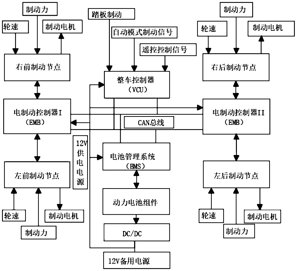
[0025] Embodiment 1: see figure 1 , a brake-by-wire brake system with power-off brakes, which includes wheel brake actuators installed at four wheels, the system also includes: two electric brake controllers (EMB), vehicle controller, 12V backup power supply.

[0026] see figure 1 , the two electric brake controllers used to control the four wheel brake actuators are respectively defined as electric brake controller I and electric brake controller II, and each electric brake controller is connected to two wheel brake actuators The electric brake controller I is connected to the wheel brake actuators of the two front wheels, and the electric brake controller II is connected to the wheel brake actuators of the two rear wheels.

[0027] exist figure 1 Among them, the vehicle controller (VCU) used to control the two electric brake controllers is connected to the two electric brake controllers through the CAN bus, and the 12V backup power supply used to provide backup power is c...

Embodiment 2

[0032] Embodiment 2: The present invention also provides a control method (hereinafter referred to as "control method") of a brake-by-wire brake system with power failure. The control method includes: S1. When the battery management system monitors that the power battery has no voltage output Information, the information is sent to the vehicle controller through the CAN bus, and the vehicle controller sends the braking force command to the electric brake controller through the CAN bus, and the electric brake controller controls the brake motor to realize vehicle braking.

[0033] As a further improvement to this embodiment, after the electric brake controller receives the wheel speed signal from the wheel speed sensor, it also includes the following steps: S2. When the received braking force command exceeds the predetermined upper limit of the braking force, the electric brake The automatic controller controls the brake motor to stop working.

[0034] A further improvement to ...


PUM


Abstract

The invention discloses a brake-by-wire system of a power-off band-type brake and a control method. The brake-by-wire system of the power-off band-type brake comprises wheel braking executing mechanisms and two electric braking controllers, a vehicle control unit and a 12V standby power supply, wherein the wheel braking executing mechanisms are mounted on four wheels, and the two electric brakingcontrollers are used for correspondingly controlling the four wheel braking executing mechanisms; each electric braking controller is connected with the two wheel braking executing mechanisms; the vehicle control unit used for controlling the two electric braking controllers is connected with the two electric braking controllers through CAN buses; and the 12V standby power supply used for providing standby power supply is connected to the vehicle control unit, the electric braking controller and a battery management system. The control method comprises the steps of transmitting information tothe vehicle control unit through the CAN bus when the battery management system monitors that a power battery has no voltage output information, enabling the vehicle control unit to transmit a brakingforce instruction to the electric braking controllers through the CAN buses, and enabling the electric braking controllers to control a braking motor to realize automobile braking. According to the brake-by-wire system of the power-off band-type brake, after an electric automobile is powered off, brake-by-wire of the band-type brake is performed to avoid the occurrence of accidents and enhance the safety.

Description

technical field [0001] The invention relates to the field of electric vehicles, in particular to a brake-by-wire brake system and control method for a power-off brake. Background technique [0002] With the worsening of environmental pollution, people's demand for zero-emission electric vehicles is increasing. Coupled with the vigorous promotion of the government, electric vehicles are becoming more and more popular. In order to improve the safety of electric vehicles, the braking of electric vehicles Increasingly demanding. [0003] At present, the electromechanical braking system based on CAN bus communication mainly consists of CAN bus network, a master control point and four slave control nodes. Through this technology, the control node receives the braking signal from the CAN bus network. The processed output is sent to the brake motor, and the brake motor drives the actuator to brake the wheels. At present, this braking method has a complex structure, low efficiency,...

Claims


Application Information

Patent Timeline
Patent Type & Authority Applications(China)
IPC IPC(8): B60T13/74B60T17/18B60L58/12B60L3/00
CPCB60L3/0046B60L58/12B60T13/74B60T17/18Y02T10/70
Inventor 高传宝蔡维福罗时海
Owner 苏州泛像汽车技术有限公司
Learn More