Cam shock wave type two-stage planar steel ball reducer

A technology of reducer and shock wave, applied in the direction of belt/chain/gear, transmission device parts, mechanical equipment, etc., can solve the problems of single-stage planar steel ball reducer being small, not very suitable for application, and increasing the size of the mechanism. Achieve the effect of reducing the weight of the whole machine, shortening the axial dimension and shortening the axial distance

Active Publication Date: 2019-11-01
YANSHAN UNIV
View PDF5 Cites 12 Cited by
  • Summary
  • Abstract
  • Description
  • Claims
  • Application Information

AI Technical Summary

Problems solved by technology

[0002] With the continuous development of movable tooth transmission, many new movable tooth reducers have come out one after another. A two-stage planar steel ball reducer (CN201910264281.4) greatly improves the transmission Efficiency, through the two-stage series connection, although a large reduction ratio transmission can be achieved, a constant-speed output mechanism is required between the primary and secondary mechanisms, resulting in a significant increase in the size of the mechanism, which is not very suitable for applications in areas limited by space size such as robot joints
Especially today with the rapid development of science and technology, there is an urgent need for a new type of transmission device with small size, light weight, and large transmission ratio. It is relatively small. If multiple single-stage planar steel ball reducers are connected in series, although a large transmission ratio can be achieved, the axial dimension is large and the application is limited. Therefore, a kind of planar steel ball reducer is developed. A two-stage planar steel ball reducer that can achieve a large transmission ratio while maintaining a small axial dimension can be applied to the development needs of more new technologies and new equipment

Method used


Image

  • Cam shock wave type two-stage planar steel ball reducer
  • Cam shock wave type two-stage planar steel ball reducer
  • Cam shock wave type two-stage planar steel ball reducer

Examples


Embodiment Construction

[0051] In order to detail the technical content, structural features, purpose and effect of the present invention, the following will be described in detail in conjunction with the accompanying drawings.

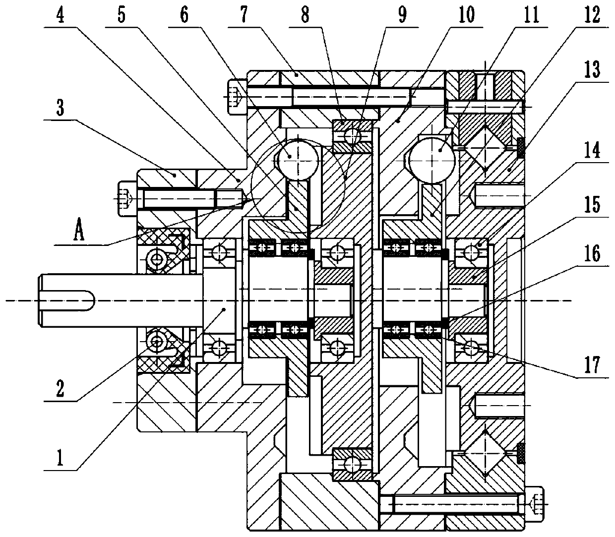
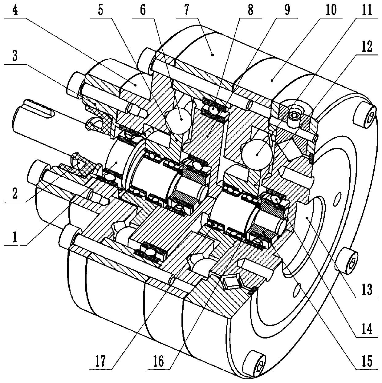
[0052] Cam shock wave type double-stage planar steel ball reducer of the present invention, such as figure 1 As shown, it includes input shaft 1, lip seal ring 2, left end cover 3, primary center wheel 4, primary shock cam 5, primary steel ball 6, housing 7, first thin-walled bearing 8, a Stage guide frame 9, secondary center wheel 10, secondary steel ball 11, secondary shock cam 12, cross roller bearing 13, deep groove ball bearing 14, sleeve cup 15, retaining ring 16 and second thin-walled bearing 17 .

[0053] Such as figure 2 As shown, the left end cover 3 is connected with the left end of the primary center wheel 4 by screws, the right end of the primary center wheel 4 and the housing 7 are fixed on the left end of the secondary center wheel 10 by screws, and the cro...


PUM


Abstract

The invention provides a cam shock wave type double-stage planar steel ball reducer. The cam shock wave type double-stage planar steel ball reducer comprises an input shaft, a lip type sealing ring, aleft end cover, a first-stage center wheel, a first-stage shock wave cam, a first-stage steel ball, a shell, a first thin-wall bearing, a first-stage guide frame, a second-stage center wheel, a second-stage steel ball, a second-stage shock wave cam, a cross roller bearing, a deep groove ball bearing, a sleeve cup, a check ring and a second thin-wall bearing. The first-stage shock wave cam and thesecond-stage shock wave cam are hinged to the corresponding shaft section through the second thin-wall bearing, the right side of the second thin-wall bearing is limited through the check ring, the left end cover is connected to the left end of the first-stage center wheel through screws, the right end of the first-stage center wheel and the shell are fixedly arranged at the left end of the second-stage center wheel through screws, and the cross roller bearing and the right end of the second-stage center wheel are fixedly connected. The cam shock wave type double-stage planar steel ball reducer has the advantages of being simple and compact in structure, high in transmission efficiency, wide in transmission ratio range, large in bearing capacity and the like, can be subjected to parameterization and serialized design and is suitable for wide application.

Description

technical field [0001] The invention relates to a movable tooth transmission device, in particular to a cam shock wave type double-stage planar steel ball reducer. Background technique [0002] With the continuous development of movable tooth transmission, many new movable tooth reducers have come out one after another. A two-stage planar steel ball reducer (CN201910264281.4) greatly improves the transmission Efficiency, through the two-stage series connection, although a large reduction ratio transmission can be achieved, a constant-speed output mechanism is required between the primary and secondary mechanisms, resulting in a significant increase in the size of the mechanism, which is not very suitable for applications in areas limited by space size such as robot joints . Especially today with the rapid development of science and technology, there is an urgent need for a new type of transmission device with small size, light weight, and large transmission ratio. It is re...

Claims


Application Information

Patent Timeline
Patent Type & Authority Applications(China)
IPC IPC(8): F16H37/12F16H57/023F16H57/021
CPCF16H37/12F16H57/021F16H57/023
Inventor 许立忠闫济东
Owner YANSHAN UNIV
Why Eureka
Try Eureka