Establishment method of power station boiler combustion intelligent distribution model

A power station boiler, an intelligent technology, applied in the combustion method, control combustion, combustion equipment and other directions, can solve the problems affecting the boiler efficiency system operation safety, the nitrogen emission can not reach the design value, the flame center deviation and other problems, achieve good Protection effect, reduction of carbon content in fly ash, and effect of stable combustion

Inactive Publication Date: 2019-11-01
杭州涌复科技有限公司
View PDF7 Cites 1 Cited by
  • Summary
  • Abstract
  • Description
  • Claims
  • Application Information

AI Technical Summary

Problems solved by technology

[0002] In recent years, with the improvement of environmental protection requirements, large-scale low-NOx combustion technology transformation has been carried out on power plant boilers, and the impact of burner transformation on boiler operating parameters has attracted the attention of production technicians; among them, the NOx emissions cannot reach The design value is a relatively common problem; and the main influencing factor of the nitride combustion technology is to change the distribution of air and dyes in the furnace; usually it is necessary to carry out reasonable air distribution. The air distribution model in the prior art is difficult to operate and has a large In the process of air distribution, if the wind speed is not uniform, it will cause the flame center of the same product to be deflected, resulting in the temperature of the heating surface in the furnace is not balanced, which seriously affects the boiler efficiency and system operation safety. Therefore, it is necessary to design a power plant boiler It is necessary to establish a method for combustion intelligent air distribution model

Method used


Image

  • Establishment method of power station boiler combustion intelligent distribution model
  • Establishment method of power station boiler combustion intelligent distribution model
  • Establishment method of power station boiler combustion intelligent distribution model

Examples


Embodiment Construction

[0023] The technical solutions of the present invention will be clearly and completely described below in conjunction with the embodiments. Apparently, the described embodiments are only some of the embodiments of the present invention, not all of them. Based on the embodiments of the present invention, all other embodiments obtained by persons of ordinary skill in the art without creative efforts fall within the protection scope of the present invention.

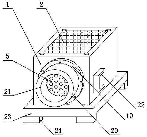
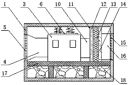
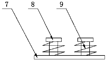
[0024] Such as Figure 1-3 As shown, a method for establishing a power plant boiler combustion intelligent air distribution model includes the following steps:

[0025] S1: For combustion boilers, the air entering the furnace mainly includes primary air and secondary air. The primary air carries pulverized coal into the furnace from the fuel nozzle, and the secondary air enters the furnace from the air nozzle through the adjusting baffle through the bellows. It is determined by the coal feeding amount of the coal mill, and...


PUM


Abstract

The invention discloses an establishment method of a power station boiler combustion intelligent distribution model. The establishment method comprises the following steps that S1, for a combustion boiler, air entering a furnace mainly comprises primary air and secondary air, primary air carries pulverized coal from a fuel nozzle to a hearth, the secondary air enters the furnace from an air nozzlethrough an adjusting baffle, primary air flow is determined by the coal feeding amount of a coal mill, and primary air flowing resistance is provided by a primary fan; the secondary air flow fed intothe furnace from the air nozzle is determined by the air box pressure and the baffle opening degree of the air nozzle, and the secondary air flow resistance is provided by an air supply device; the air distribution model is determined, so that the boiler is reasonable in air distribution; and the proportion of the air powder is reasonably adjusted, so that the combustion is relatively stable, theheat loss of the smoke can be effectively reduced, the carbon content of the fly ash can be reduced, the heat loss of the mechanical and chemical incomplete combustion of the pulverized coal can be reduced, and the boiler efficiency can be improved.

Description

technical field [0001] The invention relates to the field of boiler equipment, in particular to a method for establishing an intelligent air distribution model for power plant boiler combustion. Background technique [0002] In recent years, with the improvement of environmental protection requirements, a large-scale low-NOx combustion technology transformation has been carried out on power plant boilers. The impact of burner transformation on boiler operating parameters has attracted the attention of production technicians; among them, the NOx emissions cannot reach The design value is a relatively common problem; and the main influencing factor of the nitride combustion technology is to change the distribution of air and dyes in the furnace; usually it is necessary to carry out reasonable air distribution. The air distribution model in the prior art is difficult to operate and has a large In the process of air distribution, if the wind speed is not uniform, it will cause t...

Claims


Application Information

Patent Timeline
IPC IPC(8): F23N1/02F23C7/02G06F17/50
CPCF23C7/02F23N1/022
Inventor 刘永红
Owner 杭州涌复科技有限公司
Why Eureka
Try Eureka