Secondary combustion chamber air-distribution device of hazardous waste incineration system

A technology of air distribution device and secondary combustion chamber, which is applied to incinerators, combustion types, combustion equipment, etc., can solve the problems of increasing the diameter and height of secondary combustion chambers, increasing installation and maintenance costs, and increasing the distance traveled by flue gas. , to achieve reasonable air distribution, improve combustion effect, and reduce the effect of equipment installation

Pending Publication Date: 2019-01-11
山东福航新能源环保股份有限公司
View PDF3 Cites 0 Cited by
  • Summary
  • Abstract
  • Description
  • Claims
  • Application Information

AI Technical Summary

Problems solved by technology

In order to ensure that the flue gas residence time meets the standard, it is necessary to increase the distance that the flue gas passes in the secondary combustion chamber, which has a direct impact on the volume of the secondary combustion chamber, resulting in an increase in the diameter and height of the traditional secondary combustion chamber
As a result, the cost of equipment manufacturing is high, and the cost of installation and maintenance increases accordingly.

Method used


Image

  • Secondary combustion chamber air-distribution device of hazardous waste incineration system
  • Secondary combustion chamber air-distribution device of hazardous waste incineration system
  • Secondary combustion chamber air-distribution device of hazardous waste incineration system

Examples


Embodiment Construction

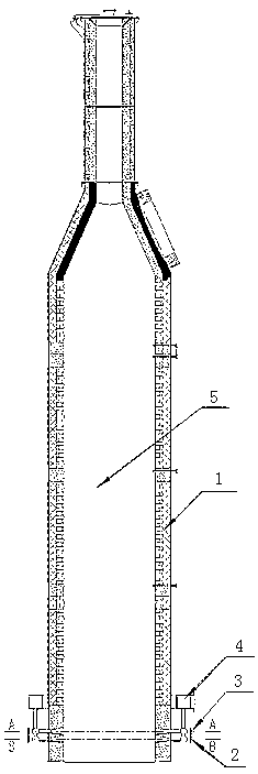
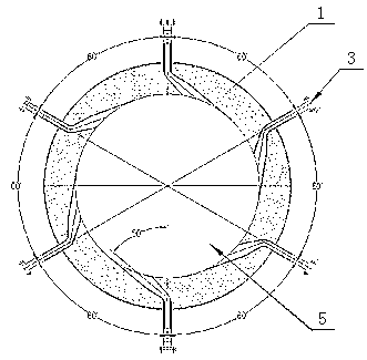
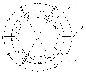
[0021] Accompanying drawing is a kind of specific embodiment of the present invention. This embodiment includes a secondary combustion chamber 1, the bottom of the secondary combustion chamber 1 is provided with bottom air inlets 2 and upper layer air inlets 3 distributed in upper and lower layers, and the bottom air inlets 2 and upper layer air inlets 3 are respectively evenly distributed in the second combustion chamber 1 There are several of the same cross-section of the furnace wall, the bottom air inlet 2 is perpendicular to the furnace wall of the second combustion chamber 1 and enters the furnace 5 along the radial direction, and the upper layer air inlet 3 is connected to the second combustion chamber 1 in a clockwise direction along the inner wall of the furnace 5 to enter.

[0022] The flue gas produced by incineration is powered by the fan 4 and enters the secondary combustion chamber 1. The structure of the secondary combustion chamber 1 is a vertical hollow cylind...


PUM


Abstract

The invention relates to the technical field of hazardous waste incineration and particularly discloses a secondary combustion chamber air-distribution device of a hazardous waste incineration system.The secondary combustion chamber air-distribution device of the hazardous waste incineration system comprises a secondary combustion chamber, and is characterized in that a plurality of bottom-layerair inlets and a plurality of upper-layer air inlets are arranged at the bottom of the secondary combustion chamber in an upper-lower two-layer distribution manner; the bottom-layer air inlets and theupper-layer air inlets are uniformly distributed in one and the same cross section of a furnace wall of the secondary combustion chamber; the bottom-layer air inlets are perpendicular to the furnacewall of the secondary combustion along the radial direction and then lead to the interior of a furnace hearth; and the upper-layer air inlets lead to the interior of the furnace hearth along the clockwise tangential direction of the inner wall of the furnace hearth, namely the direction along with which the upper-layer air inlets communicate with the secondary combustion chamber. The secondary combustion chamber air-distribution device disclosed by the invention is simple in structure and reasonable in air distribution; the flow direction and the flow rate of flue gas entering the secondary combustion chamber can be adjusted, the strong turbulence of the flue gas can be formed in the secondary combustion chamber, the national-standard flue gas residence time can be reached, and the combustion effect can be improved; and for the same air volume requirements, the height and the diameter of the secondary combustion chamber can be greatly reduced, and the equipment manufacturing cost can be reduced.

Description

(1) Technical field [0001] The invention relates to the technical field of hazardous waste incineration, in particular to an air distribution device for a second combustion chamber of a hazardous waste incineration system. (2) Background technology [0002] According to the requirements of the national standard - "Pollution Control Standards for Hazardous Waste Incineration" (GB18484-2001): the residence time of flue gas from incinerators above 1100°C is greater than 4 seconds. [0003] The implementation of this standard requires the flue gas to stay in the furnace for a certain period of time to ensure that the flue gas is completely incinerated and reduce the pollutants in the exhausted flue gas. The air inlet of the traditional secondary combustion chamber air distribution system is at the bottom, and the flue gas moves from bottom to top through the secondary combustion chamber, and finally is discharged from the top into the lower processing device. In order to ensure...

Claims


Application Information

Patent Timeline
IPC IPC(8): F23G7/00F23G5/16F23L9/00
CPCF23G5/16F23G7/00F23L9/00F23G2207/30F23G2202/103
Inventor 王志恒孙红波李林平侯芳闫广播禚林林
Owner 山东福航新能源环保股份有限公司
Why Eureka
Try Eureka