Accurate force measurement module used for conveniently replacing sensor under bridge member stress working condition
A force sensor and sensor technology, applied in the direction of the force sensor, bridge parts, bridges, etc. in the holes of the force-bearing structure, can solve the problems of affecting traffic, high labor intensity, inconvenient replacement, etc., to reduce the contact area, disassemble And the effect of convenient installation process and convenient processing
- Summary
- Abstract
- Description
- Claims
- Application Information
AI Technical Summary
Problems solved by technology
Method used
Image
Examples
Embodiment 1
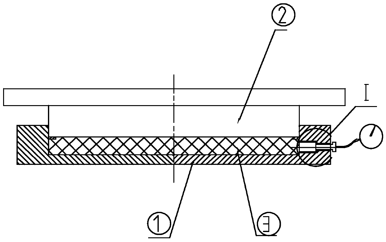
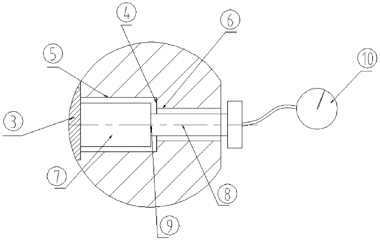
[0039] Such as Figure 1-Figure 3 As shown, in this embodiment, an accurate force measurement module for convenient replacement of sensors under the stress condition of bridge components is provided, including a pressure-bearing bottom basin 1 and a rubber pad embedded in the pressure-bearing bottom basin 1 The block 3 also includes a middle steel plate 2, which is carried above the rubber pad 3, and a top beam is carried above the middle steel plate 2, and the middle steel plate 2 is used to transmit the pressure generated by the top beam.
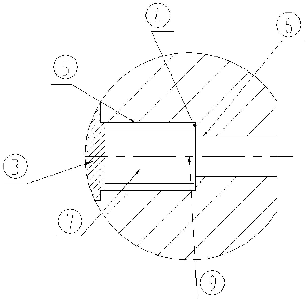
[0040] The side wall of the pressure-bearing bottom basin 1 is provided with a stepped hole along its radial direction. Of course, the stepped hole can also be arranged on the top of the middle steel plate 2 or on the bottom of the support chassis 1. The stepped hole It is composed of a small-diameter hole 6 and a large-diameter hole 5. A stepped surface 4 is formed between the small-diameter hole 6 and the large-diameter hole 5. The step...
Embodiment 2
[0048] Such as Figure 4 , Figure 5 As shown, on the basis of Embodiment 1, another accurate force-measuring module for convenient replacement of sensors under the stress condition of bridge components is provided, and its stepped hole is set as a second-order stepped hole, and the second-order stepped hole is composed of The stepped small hole 12 and the stepped large hole are formed, the stepped small hole 12 communicates with the inner cavity of the pressure-bearing bottom basin 1, the stepped large hole communicates with the outer side wall of the described pressure-bearing bottom basin 1, and the stepped large hole is installed There is an inner sleeve 11. Preferably, the inner sleeve 11 and the inner wall of the stepped large hole can be fixedly installed by threaded connection.
[0049] The force transmission plunger 7 is set as a stepped structure, the small end of the force transmission plunger 7 is movably assembled in the stepped small hole 12 and is tightly press...
Embodiment 3
[0052] Such as Figure 6 As shown, on the basis of Embodiment 1, another accurate force-measuring module for conveniently replacing the sensor under the stress condition of the bridge member is provided, and the stepped hole is set as a counterbore, and the counterbore is formed by the counterbore The small hole 14 and the large hole of the counterbore are formed, and the small hole of the countersunk head is set as a tapered hole; The walls communicate with each other and an inner sleeve is installed inside; the small end of the force transmission plunger 7 is matched with the small hole 14 of the counterbore and the end is pressed tightly against the rubber pad, and the large end of the force transmission plunger 7 The end matches the large hole of the counterbore and the end of the end is tightly pressed against the sensing surface of the load cell 8. Preferably, the inner sleeve 11 and the inner wall of the large hole of the counterbore can be fixedly installed by threaded...
PUM
 Abstract
Description
Claims
Application Information
 - R&D
- Intellectual Property
- Life Sciences
- Materials
- Tech Scout
- Unparalleled Data Quality
- Higher Quality Content
- 60% Fewer Hallucinations
Browse by: Latest US Patents, China's latest patents, Technical Efficacy Thesaurus, Application Domain, Technology Topic, Popular Technical Reports.
© 2025 PatSnap. All rights reserved.Legal|Privacy policy|Modern Slavery Act Transparency Statement|Sitemap|About US| Contact US: help@patsnap.com


