Underground diaphragm wall with pit face having water level lowering function

A technology for underground diaphragm walls and pit faces, which is applied to sheet pile walls, excavation, construction, etc., can solve the problems of occupying construction sites and high overall costs, and achieve the effect of saving construction period and cost and having strong practicability

Pending Publication Date: 2019-11-05
CHINA COAL NO 3 CONSTR GRP
View PDF0 Cites 3 Cited by
  • Summary
  • Abstract
  • Description
  • Claims
  • Application Information

AI Technical Summary

Problems solved by technology

A large-scale foundation pit project often needs to drill a large number of dewatering wells, the overall cost is high, and the construction site is occupied

Method used


Image

  • Underground diaphragm wall with pit face having water level lowering function
  • Underground diaphragm wall with pit face having water level lowering function
  • Underground diaphragm wall with pit face having water level lowering function

Examples


Embodiment Construction

[0028] See attached picture:

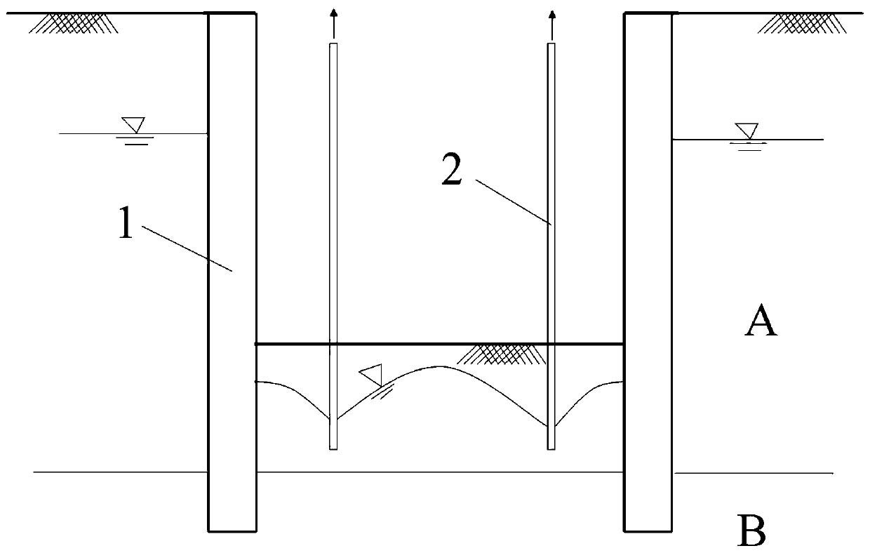
[0029] The traditional underground diaphragm wall 1 is embedded in the water-resisting layer B. The traditional underground diaphragm wall 1 blocks the penetration of groundwater outside the foundation pit to the interior of the foundation pit. It only needs to pump water inside the foundation pit to lower the water level. Digging has no effect. At present, the general practice is to install traditional dewatering wells 2 inside the foundation pit to lower the groundwater level in the pit, such as figure 1 shown.

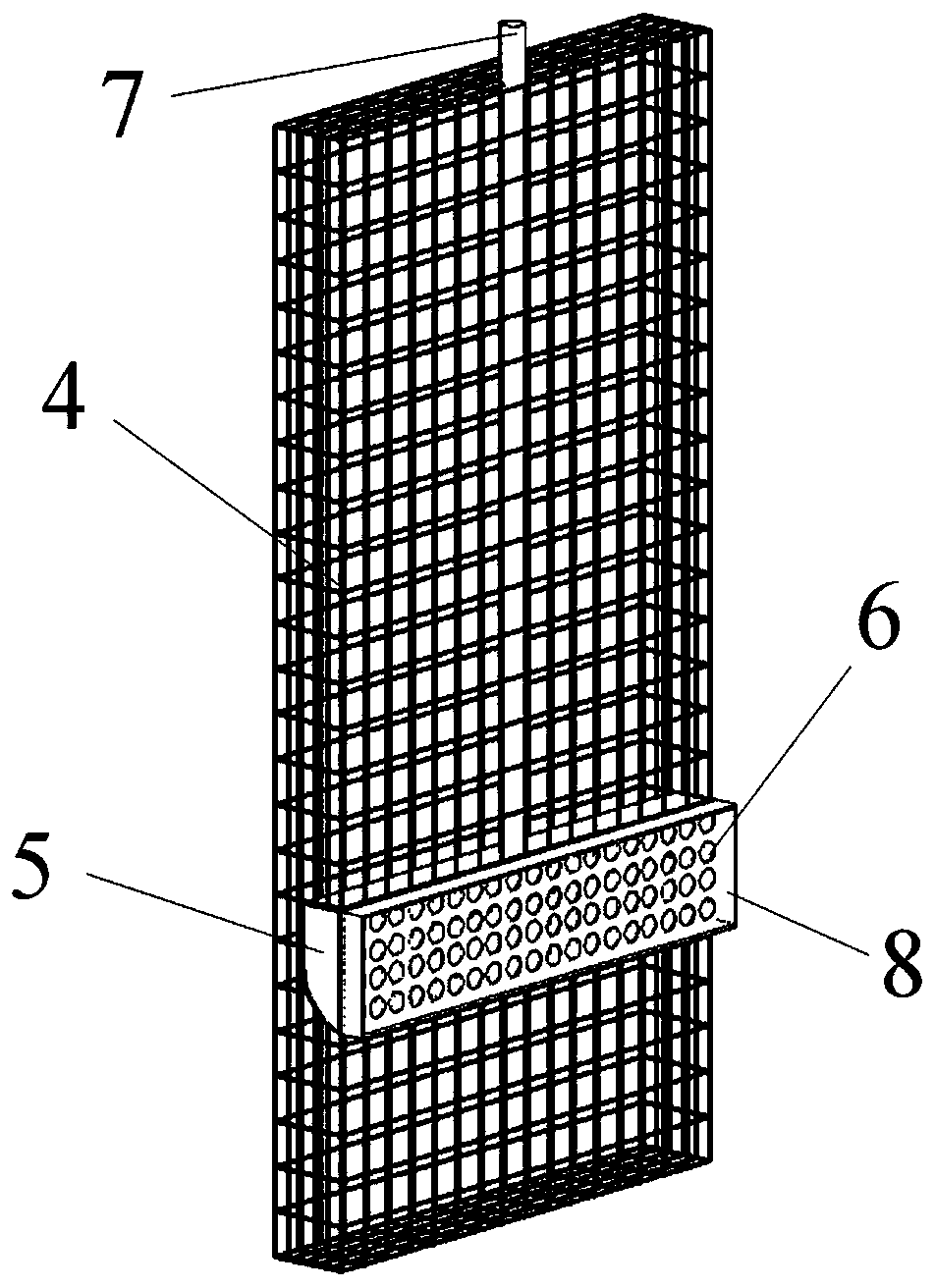
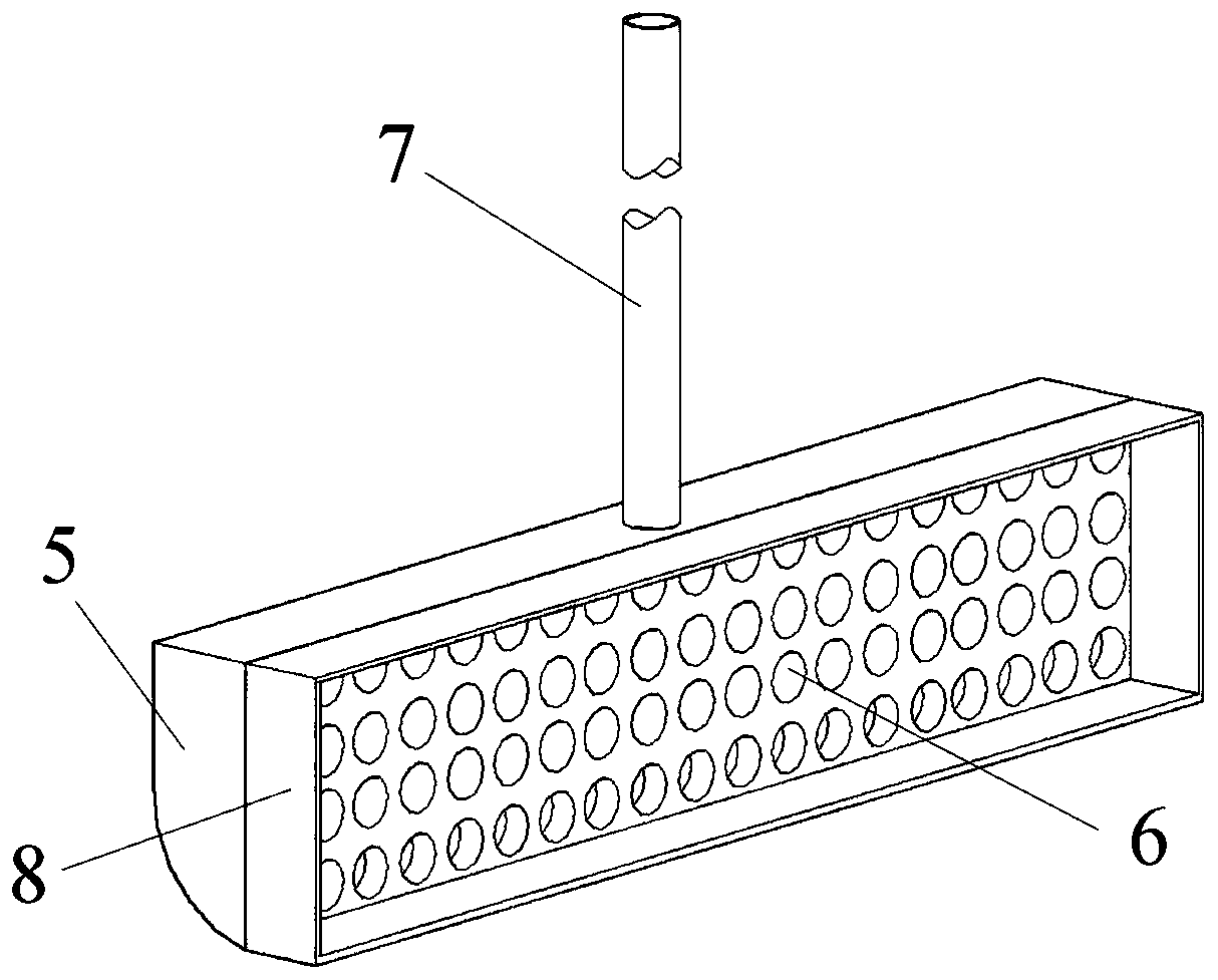
[0030] An underground continuous wall with a function of precipitation on the face of the pit, comprising a steel cage 4, a round pipe 7 and a water storage tank 5, the round pipe 7 is vertically arranged and buried in the inside of the steel cage 4, the top of the round pipe 7 is The top of the steel cage 4 protrudes, and the water storage tank 5 is fixed on the lower part of the pit face of the steel cage 4. The water storage tank ...


PUM

PropertyMeasurementUnit
porosityaaaaaaaaaa

Abstract

The invention discloses an underground diaphragm wall with a pit face having the water level lowering function. The underground diaphragm wall comprises a reinforcement cage, a circular pipe and a water storage tank, wherein the circular pipe is vertically arranged and is embedded in the reinforcement cage; the top of the circular pipe stretches out of the top of the reinforcement cage; the waterstorage tank is fixed at the lower part of the pit face of the reinforcement cage and is connected with the bottom of the circular pipe; the water storage tank and the circular pipe constitute a closed communicating system; a plurality of water inlets are formed in the earth surface of the water storage tank; and the reinforcement cage is placed in a groove and forms a cast-in-place reinforced concrete wall through the concrete pouring manner. The water storage tank is prefabricated and embedded at the lower part of the pit face of the underground diaphragm wall in advance; and after construction, the water storage tank (dewatering well) can come into use, so that a traditional dewatering well does not need to be arranged on the inner side of foundation pit engineering, and the construction period and the cost of the dewatering well are greatly shortened and reduced.

Description

technical field [0001] The invention relates to the field of underground diaphragm walls used in construction engineering, in particular to an underground diaphragm wall whose face facing a pit also has the function of dewatering. Background technique [0002] With the rapid development of urban underground space development in my country, large-scale subway systems, high-rise building basements, underground stations, and sponge city construction are all facing deep foundation pit projects. Underground diaphragm walls have become common structures for the development of deep urban underground spaces. It is mainly reflected in the fact that the underground diaphragm wall can be used as both a temporary support structure and a permanent structure. These advantages have been proven in the development of underground spaces in large cities. The underground diaphragm wall has the functions of water interception, seepage prevention, load bearing, water retaining, etc. It has good in...

Claims


Application Information

Patent Timeline
Patent Type & Authority Applications(China)
IPC IPC(8): E02D5/18E02D19/10E02D17/04
CPCE02D5/18E02D17/04E02D19/10E02D2250/0023E02D2300/0001E02D2300/0006E02D2300/0029
Inventor 董金奎曹新刚牛刚王建德丁飞张明涛杨芹杨涛李振东曹兵
Owner CHINA COAL NO 3 CONSTR GRP
Why Eureka
Try Eureka