
A device for increasing the power of a free-piston linear generator

A linear generator and piston technology, applied in free piston engines, electromechanical devices, machines/engines, etc., can solve the problems of no energy storage structure, low generator output power, low operating frequency, etc., and achieve the effect of simple structure

Active Publication Date: 2020-07-03
济南天易迅达电气科技有限公司
View PDF6 Cites 0 Cited by
  • Summary
  • Abstract
  • Description
  • Claims
  • Application Information

AI Technical Summary

Problems solved by technology

For another example, a single-cylinder two-stroke engine with an effective piston stroke of 39.8mm, a cylinder bore of 40mm, and an engine displacement of 49.9ml can have a maximum output power of 3.0kW when the operating frequency is about 125Hz, but when the operating frequency is about 40Hz , its output power is less than 1.1kW
[0004] Existing back-mounted type is all provided with motor at both ends of generator mandrel shaft at present (as attached figure 2 ), the two-stroke engine is generally selected to be symmetrically arranged, but because there is no energy storage structure, the operating frequency is low, which in turn leads to low output power of the generator, so that the advantages of FPLG are not brought into play

Method used


Image

  • A device for increasing the power of a free-piston linear generator
  • A device for increasing the power of a free-piston linear generator
  • A device for increasing the power of a free-piston linear generator

Examples


Embodiment Construction

[0034] In order to clearly illustrate the technical features of the present solution, the present invention will be described in detail below through specific implementation methods and in conjunction with the accompanying drawings. The following disclosure provides many different embodiments or examples for implementing different structures of the present invention. To simplify the disclosure of the present invention, components and arrangements of specific examples are described below. Furthermore, the present invention may repeat reference numerals and / or letters in different instances. This repetition is for the purpose of simplicity and clarity and does not in itself indicate a relationship between the various embodiments and / or arrangements discussed. It should be noted that components illustrated in the figures are not necessarily drawn to scale. Descriptions of well-known components and processing techniques and processes are omitted herein to avoid unnecessarily lim...


PUM


Abstract

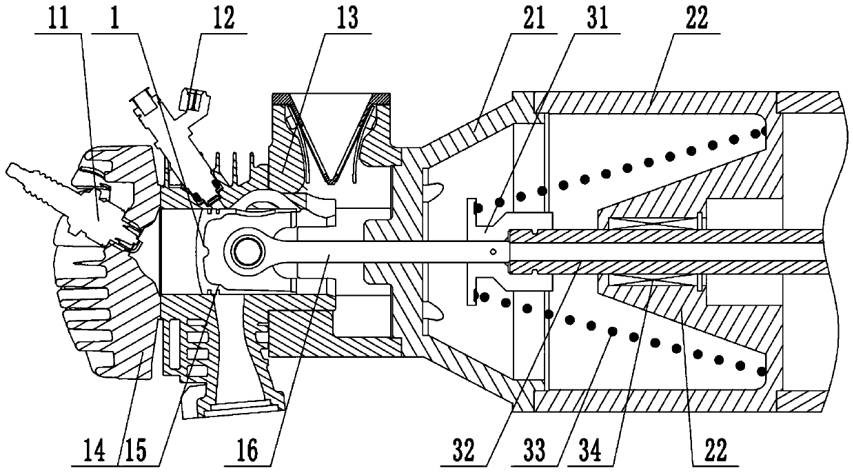
The invention discloses a power improvement device of a free piston linear generator. The power improvement device of the free piston linear generator comprises a power part. The power part comprisesan air cylinder body, a cylinder cover, a spark plug, an oil injector, a piston and a piston rod. The spark plug is installed on the cylinder cover, the oil injector is installed on the air cylinder body, the piston is arranged in the air cylinder body, and the piston rod is connected to the piston. The power improvement device of the free piston linear generator further comprises a stator part and a rotor part. The stator part comprises a generator stator. The rotor part comprises a generator rotor, a rotor mandrel and springs. The generator rotor cooperates with the generator stator, and therotor mandrel is connected with the generator rotor and connected with the piston rod. One end of each spring is connected with the generator stator, and the other end of each spring is connected with the piston rod. One end of each spring is connected to the generator stator, so that the position fixing is guaranteed; and the other end of each spring is connected with the piston rod, and stretches out and draws back along with the movement of the piston rod, so that the effect of energy storage is achieved. The rigidity of the corresponding springs is obtained through calculation and simulation, the springs which provide the corresponding frequencies can be obtained, and therefore the free piston linear generator can achieve the high frequency, and the advantage of the free piston lineargenerator can be fully achieved.

Description

technical field [0001] The invention relates to the technical field of range extenders for new energy vehicles, in particular to a power-enhancing device for a free-piston linear generator. Background technique [0002] At present, the common free-piston linear generator (FPLG) structures are mainly divided into three types: single-piston type, opposed double-piston type (referred to as opposed type) and back-mounted double-piston type (referred to as back-mounted type). The single-piston type has a simple structure and is easy to control, but there is an imbalance problem and requires a return device; the opposed type has good balance, but requires a synchronization mechanism and a return device; the back-mounted type has higher energy density and higher thermal efficiency. [0003] Although the thermal efficiency of FPLG is higher than that of conventional engines, the operating frequency of FPLG is very low due to the lack of flywheel to store energy. For example, a prot...

Claims


Application Information

Patent Timeline
Patent Type & Authority Patents(China)
IPC IPC(8): F02B71/04H02K35/00
CPCF02B71/04H02K35/00
Inventor 唐娟徐伟王安勇刘忠宝
Owner 济南天易迅达电气科技有限公司
Learn More