Optical window based on double-self-focusing lens structure

A technology of self-focusing lens and optical window, which is applied in the direction of offensive equipment, blasting barrels, weapon accessories, etc., can solve the problems of ignition failure, power density drop, optical device and optical fiber damage, etc., to improve the receiving rate, reduce randomness, and improve The effect of high temperature and high chamber pressure capabilities

Inactive Publication Date: 2019-11-05
NANJING UNIV OF SCI & TECH
View PDF4 Cites 4 Cited by
  • Summary
  • Abstract
  • Description
  • Claims
  • Application Information

AI Technical Summary

Problems solved by technology

This kind of optical window has a simple structure but has many disadvantages: there is a divergence angle for the laser. After the laser passes through the optical window, the spot area increases and the power density decreases greatly, which in turn requires a large laser ignition threshold power and ignition reliability for successful ignition. Margin reduction
Moreover, this structure is not conducive to the self-inspection of the optical path system, that is, in this structure, the reflectivity of each pyrotechnic device is very random, making it difficult to formulate a quantitative criterion for the continuity detection of the optical path
When igniting, the chamber pressure generated by the agent in the igniter is relatively high, which will easily damage or shatter the optical window of the self-focusing structure, resulting in a drop in chamber pressure or even ignition failure, and may cause damage or destruction to the optical devices and optical fibers at the front end

Method used


Image

  • Optical window based on double-self-focusing lens structure
  • Optical window based on double-self-focusing lens structure
  • Optical window based on double-self-focusing lens structure

Examples


Embodiment Construction

[0025] The present invention will be further explained in detail below in conjunction with the accompanying drawings and embodiments.

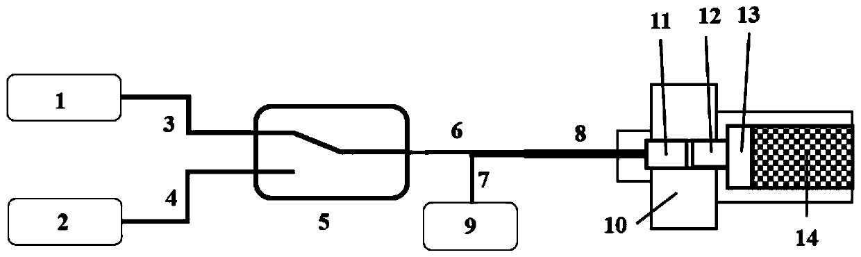
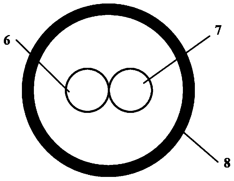
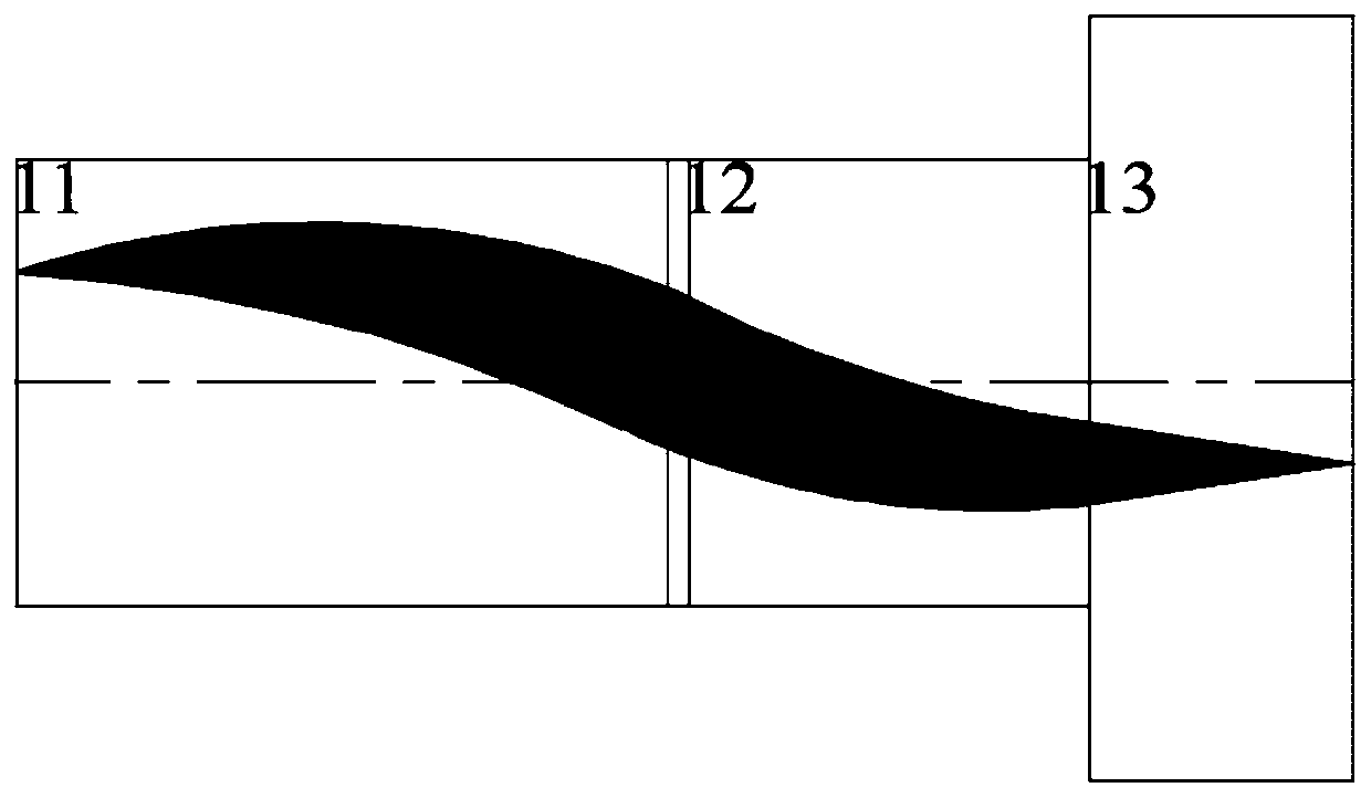
[0026] Such as figure 1 As shown, a pressure-resistant optical window based on a double self-focusing lens structure, the window includes: ignition laser 1, detection laser 2, ignition input fiber 3, detection input fiber 4, optical switch 5, ignition fiber 6, detection fiber 7, Photodetector 9, this window also includes: first self-focusing lens 11, second self-focusing lens 12 and sapphire transparent window 13; Described ignition laser 1 is connected with optical switch 5 by ignition input optical fiber 3; Described detection laser 2 The optical switch 5 is connected with the optical switch 5 through the detection input fiber 4; the optical switch 5 is connected with the first self-focusing lens 11 through the ignition fiber 6; the photodetector 9 is connected with the first self-focusing lens 11 through the detection optical fiber 7; The ...


PUM


Abstract

The invention belongs to the field of laser initiating explosive devices, and particularly relates to an optical window based on a double-self-focusing lens structure. The optical window comprises anignition laser, a detection laser, an optical switch, a photoelectric detector, a first self-focusing lens, a second self-focusing lens and a sapphire transparent window, wherein the ignition laser isconnected to the optical switch through an ignition input fiber and a detection input fiber correspondingly, the optical switch is connected with the first self-focusing lens through the ignition optical fiber, the photoelectric detector is connected with the first self-focusing lens through the detection optical fiber, the second self-focusing lens and the sapphire transparent window are sequentially placed behind the first self-focusing lens, and optical axes of the first self-focusing lens, the second self-focusing lens and the sapphire transparent window are coaxial. According to the optical window, the technical defects of an existing laser initiating explosive device optical window are overcome, the laser radiation power density is avoided, a certain proportion of detection light isguaranteed to enter the detection optical fiber, the consistency of the reflectivity of the initiating explosive devices is improved, and the capability of the chamber pressure resistance of the optical window is improved.

Description

technical field [0001] The invention belongs to the field of laser pyrotechnics, in particular to an optical window based on a double self-focusing lens structure. Background technique [0002] In the laser ignition / detonation system, the laser transmits energy through the optical fiber to the surface of the ignition agent of the transducer element, thereby igniting or detonating the pyrotechnics. The laser ignition and detonation system requires detection of the continuity of the entire optical path system, so a laser pyrotechnics optical window part is required to reflect part of the incident light of the detection light to the detection fiber, and quantitatively detect the reflection from the optical window into the detection fiber through photoelectric conversion The optical power of the detected light can be used to judge the continuity of the entire optical system. [0003] The traditional optical window of laser pyrotechnics is a circular flat glass located between t...

Claims


Application Information

Patent Timeline
Patent Type & Authority Applications(China)
IPC IPC(8): F42B3/113
CPCF42B3/113
Inventor 吴立志曹金乐沈瑞琪
Owner NANJING UNIV OF SCI & TECH
Why Eureka
Try Eureka