Optical radar apparatus

A lidar and light-like technology, which is applied to measurement devices, re-radiation of electromagnetic waves, utilization of re-radiation, etc., can solve problems such as insufficient distance measurement accuracy, weakened laser intensity, etc., and achieve the effect of cost reduction.

Active Publication Date: 2019-11-05
SHARP KK
View PDF12 Cites 1 Cited by
  • Summary
  • Abstract
  • Description
  • Claims
  • Application Information

AI Technical Summary

Problems solved by technology

[0004] The collective irradiation type is easy to downsize because it does not require a mechanical mechanism, but compared with the scanning type, the laser intensity on the target is weakened
Therefore, as the distance to the object increases, the signal strength decreases and the accuracy of distance measurement decreases.
[0005] On the other hand, when the laser beam is shaped into a line and scanned in only one direction (refer to Patent Document 3), the light irradiation intensity is improved compared with collective irradiation, but it is not sufficient.

Method used


Image

  • Optical radar apparatus
  • Optical radar apparatus
  • Optical radar apparatus

Examples


no. 1 approach 〕

[0042] (Lidar device)

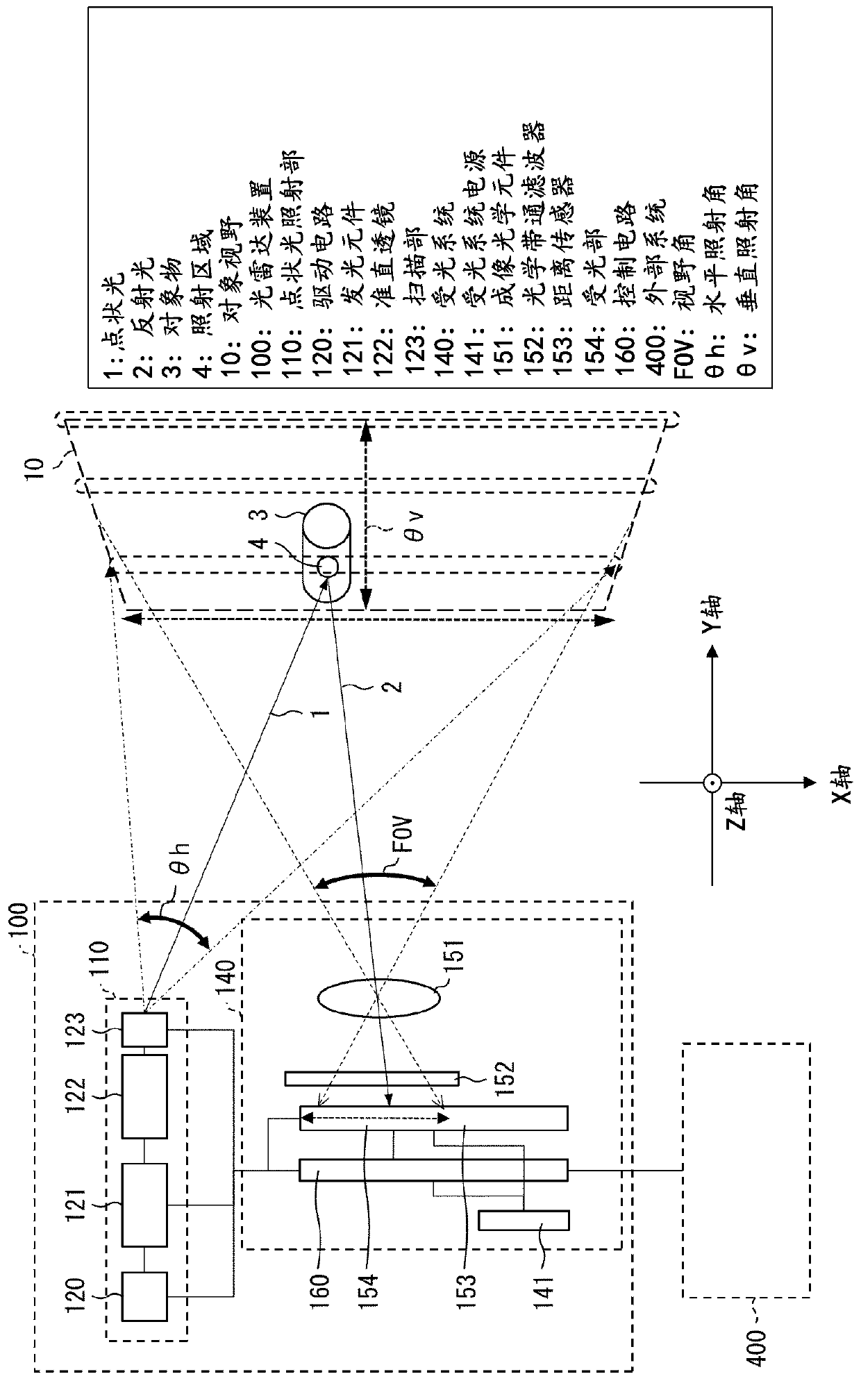
[0043] according to Figure 1 to Figure 11 , the configuration of the lidar device 100 according to the first embodiment of the present invention will be described. The following description will be made using a right-handed coordinate system in which the Y-axis is the direction in front of the lidar device 100 and the Z-axis is the vertical direction of the paper. Such as figure 1 and figure 2 As shown, the lidar device 100 is composed of a point light irradiation unit 110 that irradiates a point light 1 on an object 3 , and a light receiving system 140 that receives reflected light 2 from the object 3 within the target field of view 10 .

[0044] (point light irradiation part)

[0045] The point light irradiation unit 110 includes a light emitting element 121 , a drive circuit 120 (including a power supply), a collimator lens 122 and a scanning unit 123 . The light emitting element 121 is a member that emits point light. The driving circuit 120...

no. 1 example

[0149] Next, at a point 20 m away from the lidar device 100, a white wall is set as an object, and point light B(s, t) is irradiated within the range of s=0 to 40 and t=0 to 20, About the combination of each s, t Figure 9 The selection process of the column and row shown. In addition, it is preferable that the installation position of the test body is as far away as possible. Preferably close to the maximum measurement distance if possible. An effective activation region 5 can thus be determined in the vicinity of the maximum measuring distance. The above process was carried out in the dark.

[0150] As a result, Zb-Za=5 and Xb-Xa=46 on average. That is, the effective average number of SPADs as the activated region 5 is 5×46=230. An example of the average measurement data is shown in Figure 10 middle. The activated area is much smaller than the area where the reflected light signal is detected. The distribution normalized by the peak value of the average value of the...

no. 2 example

[0152] The test body is placed at a position 200 m away from the lidar device 100, and the results of the time-of-flight measurement are shown in Figure 11 middle. The measurements were taken on a clear day in July with very strong background light. The photon count based on background light was a maximum of 14 and an average of 4.0. At a distance of 200m, a sufficiently large signal can also be obtained with the maximum background light signal. In repeated measurements, the average signal from the test subjects was 26.7, a maximum of 36, and a minimum of 16. Therefore, approximately 200 m can be used as the maximum measurement distance in this configuration. In addition, objects can be detected smoothly even at the shortest distance of 2m.

[0153] According to the above method, in this configuration, the point beam is scanned two-dimensionally by the non-mechanical scanning system, and the reflected light is imaged on the light receiving part of the distance sensor by t...


PUM


Abstract

The present invention provides a non-mechanical-scanning-type optical radar apparatus that is capable of long distance measurement and its cost is reduced. The optical radar apparatus (100) includes:a light emitting section (110); and a light receiving system (140), the light receiving system (140) at least including a focusing optical element (151) and a distance sensor (153) that includes a light receiver (154), the target field of view being projected on the light receiver (154) through the focusing optical element (151), the distance sensor (153) being configured to set an activation region in a part of the light receiver (154) depending on the scanning with the light and measure a distance to the object with use of a signal from the activation region (5).

Description

technical field [0001] The present invention relates to a light radar device for measuring the distance to an object. Background technique [0002] A 3D picture is a concept that includes distance information to objects within the field of view in addition to a 2D picture such as a normal photo. In recent years, it has been widely used for peripheral recognition of cars and robots. As a method of measuring high-precision distance information, a method of measuring the time-of-flight (ToF) until the laser light is reflected from an object after being irradiated with a laser beam and returns. [0003] As a method of irradiating laser light toward the field of view, there is a rotary type (see Patent Documents 1 and 2) in which a light emitting unit that irradiates a laser beam (spot beam) that is approximately parallel and collimated within a narrow range and a light receiving device are integrally rotated (see Patent Documents 1 and 2) or by reflection A scanning method in w...

Claims


Application Information

Patent Timeline
Patent Type & Authority Applications(China)
IPC IPC(8): G01S17/08G01S17/10G01S7/481G01S7/486G01S7/4863
CPCG01S17/08G01S7/4817G01S7/4816G01S7/486G01S7/4863G01S17/42G01S7/4868
Inventor 井口胜次
Owner SHARP KK
Why Eureka
Try Eureka