
Inductance element and filter

A technology of inductive components and filters, applied in the direction of inductors, electrical components, printed inductors, etc., can solve the problems of inability to completely filter out common mode signals, low consistency, low yield, etc. performance effect

Pending Publication Date: 2019-11-05
SHENNAN CIRCUITS
View PDF0 Cites 0 Cited by
  • Summary
  • Abstract
  • Description
  • Claims
  • Application Information

AI Technical Summary

Problems solved by technology

[0004] The technical problem mainly solved by this application is to provide an inductance element and a filter to solve the technical problems that the inductance element cannot completely filter out the common mode signal and the consistency is not high, and the yield rate is low in the prior art.

Method used


Image

  • Inductance element and filter
  • Inductance element and filter
  • Inductance element and filter

Examples


Embodiment Construction

[0017] The following will clearly and completely describe the technical solutions in the embodiments of the present application. Obviously, the described embodiments are only some of the embodiments of the present application, rather than all the embodiments. Based on the embodiments in this application, all other embodiments obtained by persons of ordinary skill in the art without making creative efforts belong to the scope of protection of this application.

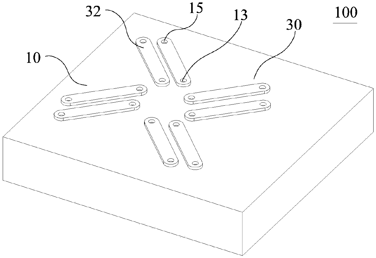
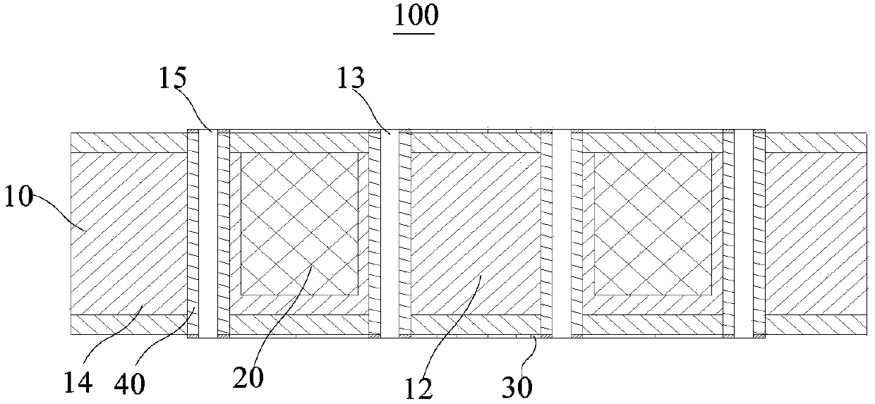
[0018] In one aspect, the present application provides an inductance element 100 . Please also refer to Figure 1 to Figure 3 , in this embodiment, the inductance element 100 generally includes: a substrate 10 , a magnetic core 20 embedded in the substrate 10 , two transmission line layers 30 located on opposite sides of the substrate 10 , and a plurality of conductive elements 40 .

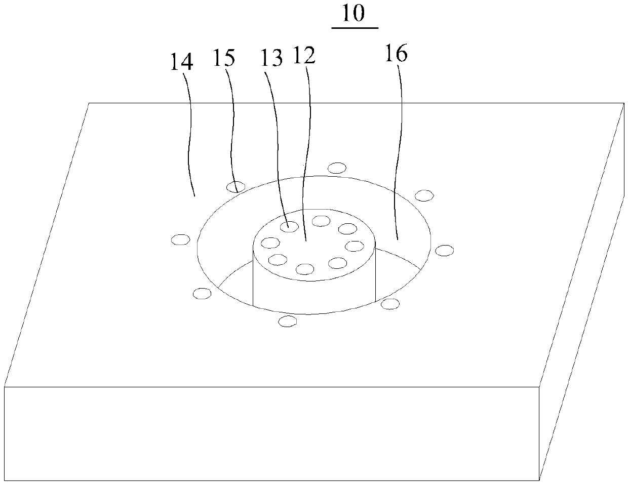
[0019] Among them, such as image 3 As shown, in this embodiment, the substrate 10 may include a central portion 12 and a peripheral po...


PUM

PropertyMeasurementUnit
Thicknessaaaaaaaaaa

Abstract

The invention discloses an inductance element and a filter. The inductance element comprises a substrate, a magnetic core, transmission line layers and multiple conductive members, wherein an annularaccommodating groove in the substrate defines the substrate into a central part and a peripheral part; multiple internal and external via holes are formed in the central part and the peripheral part respectively; the magnetic core is accommodated into the annular accommodating groove; at least one transmission line layer is arranged at each of two sides of the substrate; each transmission line layer comprises multiple lead patterns connected among the internal and external via holes; the plurality of conductive members arranged in the internal and external via holes are connected with the leadpatterns in sequence to form a coil loop winding the magnetic core; the lead patterns on the same transmission line layer are divided into multiple groups of line patterns; and the routing directionsof two adjacent lead patterns in each group are kept consistent. The coil loop winding the magnetic core is formed on the substrate, so that the routing directions of the adjacent lead patterns are kept consistent, thereby improving the filter performance of the inductance on a common-mode signal.

Description

technical field [0001] The present application relates to the technical field of integrated circuits, in particular to an inductance element and a filter. Background technique [0002] The common-mode inductor is a common-mode interference suppression device with a ferrite core, which has a suppression effect on common-mode signals, but has little effect on differential-mode signals. The working principle of the common-mode inductor is that when the common-mode current flows, the magnetic flux in the magnetic ring superimposes on each other, thus having a considerable inductance, which inhibits the common-mode current, and when the two coils flow through the differential-mode current, The magnetic flux in the magnetic ring cancels each other, and there is almost no inductance, so the differential mode current can pass without attenuation. Therefore, common-mode inductors can effectively suppress common-mode interference signals in a balanced line, but have no effect on diff...

Claims


Application Information

Patent Timeline
IPC IPC(8): H01F17/06H01F17/00H01F27/28H01F27/26H03H1/00
CPCH01F17/06H01F17/0006H01F27/2804H01F27/266H03H1/00H01F2017/0093H01F2017/0073H01F2027/2814H03H2001/0085
Inventor 曾浴华郭伟静史庚才
Owner SHENNAN CIRCUITS
Learn More