Improvement method for low noise structure and sound absorbing structure of indoor substation

A substation and low-noise technology, applied in the direction of transformer/inductor noise damping, circuits, electrical components, etc., can solve the problems of excessive noise electrical equipment, layout design not considered, and limited noise reduction methods, etc., to achieve low cost and improve The effect of sound absorption performance

Active Publication Date: 2019-11-05
WUHAN UNIV
View PDF4 Cites 3 Cited by
  • Summary
  • Abstract
  • Description
  • Claims
  • Application Information

AI Technical Summary

Problems solved by technology

The currently followed indoor substation design process is "electrical design - civil engineering design - noise level detection - noise reduction design". Different design departments are independent of each other. The noise reduction methods adopted by each department are limited, and the noise reduction methods are regarded as remedial measures. It is not a preventive measure. For example, the civil engineering design department can only modify the civil engineering design part. After the noise level exceeds the standard, the civil engineering design department can only adopt the method of installing a sound insulation wall. However, the reason for the excessive noise may be that the layout design of electrical equipment does not take into account the transformer. The sound radiation characteristics of the substation, such a design process lacks feedback information between various design departments, and cannot find a most cost-effective way to reduce substation noise

Method used


Image

  • Improvement method for low noise structure and sound absorbing structure of indoor substation
  • Improvement method for low noise structure and sound absorbing structure of indoor substation
  • Improvement method for low noise structure and sound absorbing structure of indoor substation

Examples


Embodiment Construction

[0051] In order to make the purpose and technical solution of the present invention clearer and more specific, the present invention will be further described in detail below with reference to the accompanying drawings and examples. It should be understood that the specific embodiments described here are only used to explain the present invention, not to limit the present invention.

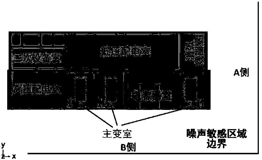
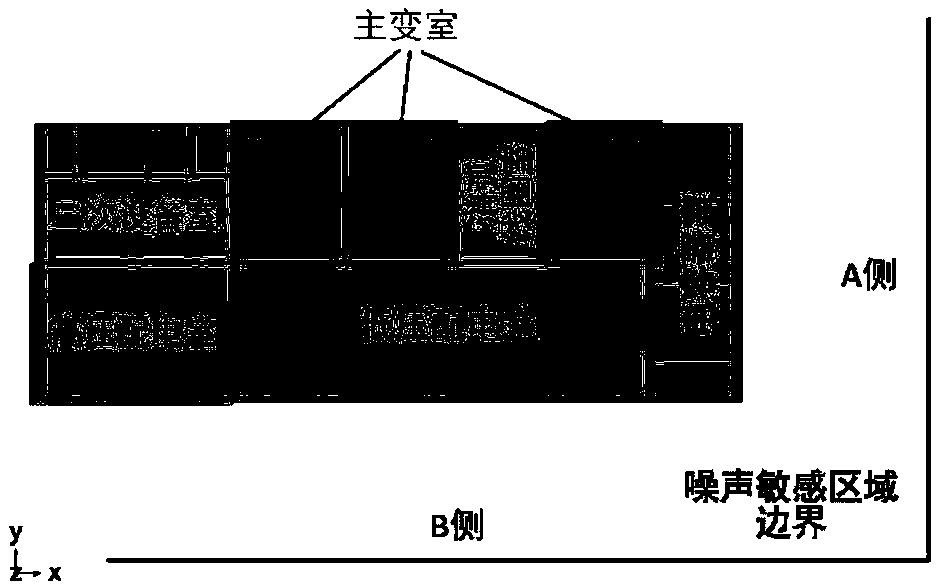
[0052] refer to Figure 2a and Figure 2b , according to the analysis results of the sound radiation characteristics, the position of the transformer room is adjusted to keep it away from the noise-sensitive area under the premise of neutral land cost; on the basis of ensuring the heat dissipation efficiency, the central height of the ventilation window is reduced from 6 meters to 5.1 meters, In order to reduce the direct spread of higher sound pressure level noise on the higher level of the transformer room, and at the same time change the orientation of the ventilation window to avoid it from ...


PUM

PropertyMeasurementUnit
heightaaaaaaaaaa

Abstract

The present invention relates to an improvement method for a low noise structure and a sound absorbing structure of an indoor substation. The method visualizes and quantifies an external sound field of a power transformer through acoustic radiation characteristics analysis, combines acoustic radiation characteristics of the power transformer with feedback information between design departments toimprove and optimize an overall layout and the sound absorbing structure of the indoor substation, to reduce sound pressure level at the boundary of a noise sensitive area. Optimization of the overalllayout of the indoor substation includes adjusting position of a transformer vault away from the noise sensitive area, reducing height of a clearstory and changing orientation of the clearstory; Improvements of the sound absorbing structure include increasing depth of a cavity of the sound absorbing structure, attaching a metal film to inside of a foam metal sound absorbing panel, and changing position of some sound absorbing material. The method analyzes the acoustic radiation characteristics through impedance tube comparison test and establishing a 3D multiphysics coupling model. The improved sound absorbing structure can effectively improve overall sound absorption effect and reduce sound radiation level of the substation.

Description

technical field [0001] The invention relates to the field of passive noise control, in particular to a passive noise control system for an indoor substation power transformer. Background technique [0002] With the advancement of urbanization and old city revitalization plans, people's pursuit of convenient, orderly and efficient lifestyles has increased the demand for electric energy; Adjacent to residential areas. Unlike suburban substations, which have sufficient space to reduce noise from power transformers, urban areas have limited space and stricter environmental noise standards, making indoor substations with a smaller footprint a preferred choice for designers and operators. The currently followed indoor substation design process is "electrical design—civil engineering design—noise level detection—noise reduction design". Different design departments are independent of each other. The noise reduction methods adopted by each department are limited, and the noise redu...

Claims


Application Information

Patent Timeline
Patent Type & Authority Applications(China)
IPC IPC(8): H01F27/33H01F41/00G06F17/50
CPCH01F27/33H01F41/00
Inventor 应黎明王东晖张露王晋伟
Owner WUHAN UNIV
Why Eureka
Try Eureka