Shielding structure design method for staggered winding transformer of flyback power supply

A technology of shielding structure and design method, applied in the direction of inductance/transformer/magnet manufacturing, transformer/inductor coil/winding/connection, preventing/reducing unwanted electric/magnetic influence, etc., can solve common mode noise, power supply It is difficult for the product to meet the relevant EMC standards, electronic load interference and other issues, so as to achieve the effect of reducing weight and volume, significant suppression effect and increasing product cost

Inactive Publication Date: 2019-11-05
ZHEJIANG UNIV
View PDF1 Cites 4 Cited by
  • Summary
  • Abstract
  • Description
  • Claims
  • Application Information

AI Technical Summary

Problems solved by technology

With the switching characteristics of switching devices getting better and better, high dv / dt and di / dt will bring serious EMI problems. On the one hand, these serious EMI problems will make it difficult for power supply products to meet relevant EMC standards. On the other hand, even if Meet the relevant EMC standards, sometimes common mode noise will be formed on the more sensitive load side, causing serious interference to electronic loads
[0006] In theory, if the length, thickness and position of the shielding layer are fixed, the common mode current in the transformer can be minimized by properly adjusting the width, thereby suppressing the common mode noise on the load side to the lowest level, but how to quantitatively design this index is difficult to quickly effective realization

Method used


Image

  • Shielding structure design method for staggered winding transformer of flyback power supply
  • Shielding structure design method for staggered winding transformer of flyback power supply
  • Shielding structure design method for staggered winding transformer of flyback power supply

Examples


Embodiment Construction

[0042]In order to describe the present invention more specifically, the technical solutions of the present invention will be described in detail below in conjunction with the accompanying drawings and specific embodiments.

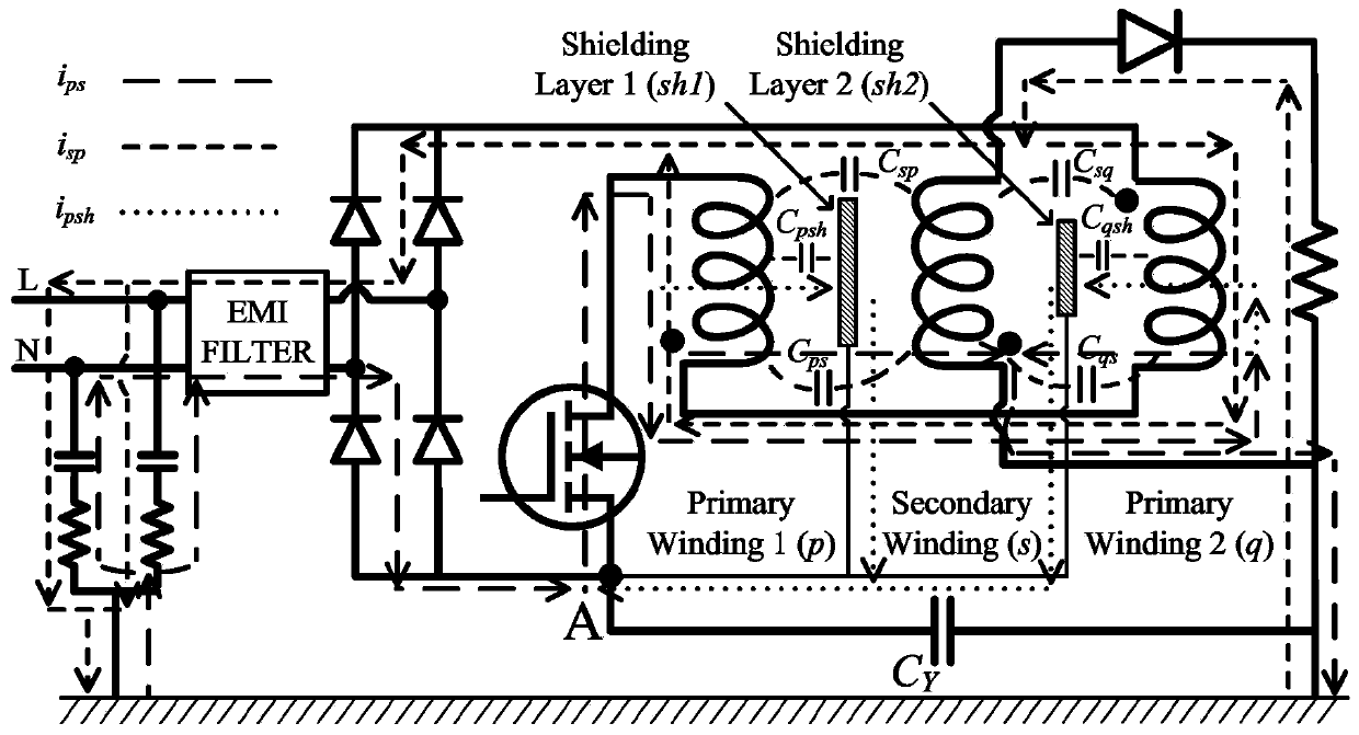
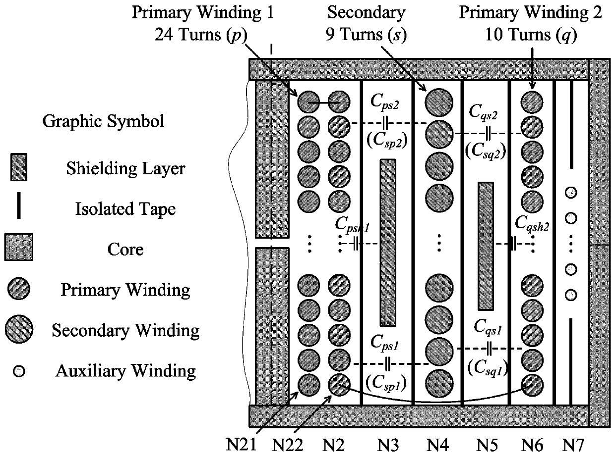
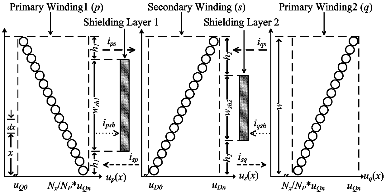
[0043] The design method of the shielding structure of the interleaved winding transformer of the flyback power supply of the present invention uses finite element analysis software to simulate the structural capacitance between the primary-secondary-primary windings and the gap between the primary and secondary windings and the shielding layer under different widths of the double copper foil shielding layer. The structural capacitance between them, and then use the common-mode current evaluation formula to calculate the shielding layer width when the common-mode current is minimum, including the following steps:

[0044] (1) Measure and estimate the structural dimensions of the interleaved winding transformer, such as the winding diameter, the thickness of...


PUM

PropertyMeasurementUnit
thicknessaaaaaaaaaa

Abstract

The invention discloses a shielding structure design method for a staggered winding transformer of a flyback power supply. According to the method, the design burden of a filter is not increased, simulation and calculation are adopted in the whole design process and the additional material cost is not increased. In addition, the weight and the volume of a staggered wound transformer device are reduced; shielding layers are relatively light and relatively thin, so that the weight or the volume of the transformer or a whole power supply device is not increased; common-mode noise is suppressed toa certain extent through designing appropriate double copper foil shielding layers in the transformer, the design burden of a common-mode filter is reduced and the weight and the volume of the filtercan be appropriately reduced, thereby reducing the weight and the volume of the whole device. Meanwhile, the suppression effect on the common-mode noise is very significant; the common-mode noise ata load side of a flyback circuit is suppressed by using the double copper foil shielding layers of the staggered wound transformer designed by the method; and the suppression effect, on the common-mode noise, of the double copper foil shielding layers is obviously better than that of a traditional shielding layer.

Description

technical field [0001] The invention belongs to the technical field of shielding design of switching power supply transformers, and in particular relates to a shielding structure design method of a flyback power supply interleaved winding transformer. Background technique [0002] Due to its isolation function, the flyback switching power supply is widely used in communication, service systems and low-power electronic equipment. These devices need to meet the relevant electromagnetic compatibility (EMC) standards, so there is often a certain amount of electromagnetic interference in the design of switching power supply products. (EMI) filtering measures. With the switching characteristics of switching devices getting better and better, high dv / dt and di / dt will bring serious EMI problems. On the one hand, these serious EMI problems will make it difficult for power supply products to meet relevant EMC standards. On the other hand, even if To meet the relevant EMC standards, ...

Claims


Application Information

Patent Timeline
Patent Type & Authority Applications(China)
IPC IPC(8): H01F41/00H01F27/36H01F27/28
CPCH01F27/28H01F27/36H01F41/00
Inventor 陈恒林刘冠辰
Owner ZHEJIANG UNIV
Why Eureka
Try Eureka