electrical connector

A technology for electrical connectors and electrical connections, which is applied in the direction of connection, parts of connection devices, circuits, etc., which can solve the problems of long terminal current path, limit transmission rate, and affect high-frequency characteristics, so as to increase transmission speed and improve High-frequency characteristics, the effect of shortening the current path

Active Publication Date: 2022-07-26
FUDING PRECISION COMPONENTS SHENZHEN +1
View PDF12 Cites 0 Cited by
  • Summary
  • Abstract
  • Description
  • Claims
  • Application Information

AI Technical Summary

Problems solved by technology

[0002] Chinese Utility Model Patent No. CN206283019U discloses an electrical connector for mounting on a circuit board to electrically connect a chip module, which includes an insulating body and conductive terminals held on the insulating body. The holding part of the insulating body, the elastic arm bent upward from the holding part and extending out of the upper surface of the insulating body, and the welding part extending downward from the holding part to be welded to the circuit board, when the chip module presses down on the elastic When the arms are connected, the conductive terminals form an electrical connection between the chip module and the circuit board. Due to the current requirements for the transmission speed of high-frequency signals for electrical connectors are continuously increasing, and the elastic arms of such conductive terminals are due to abutment It has to be set in a curved long arm shape due to the demand, which will cause the current path of the terminal to be too long, which will affect its high frequency characteristics and limit its transmission rate

Method used


Image

  • electrical connector
  • electrical connector
  • electrical connector

Examples


Embodiment Construction

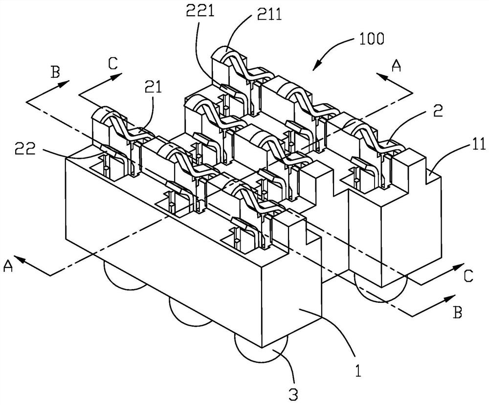
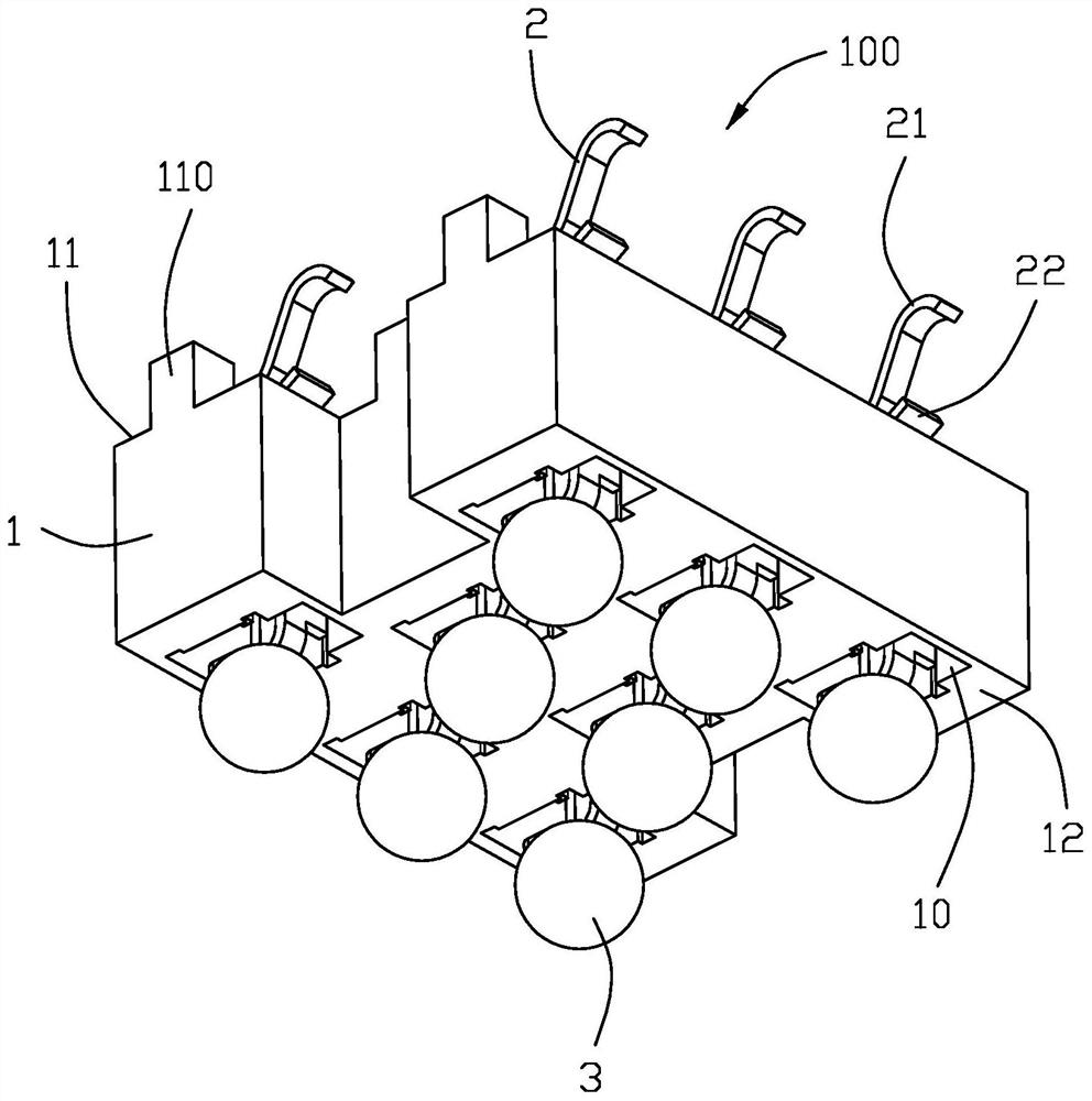
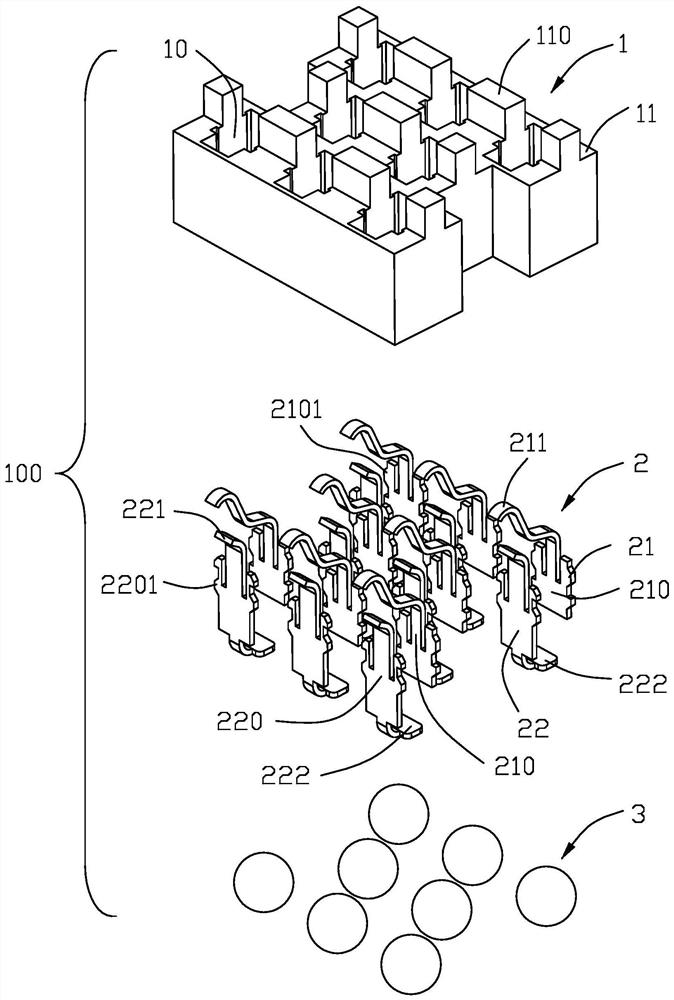
[0040] Below, will combine Figure 1 to Figure 9 The specific embodiments of the electrical connector of the present invention are introduced.

[0041] The electrical connector 100 of the present invention is used for soldering to a circuit board (not shown) to electrically connect a chip module 200, such as Figure 1 to Figure 7 As shown, the electrical connector 100 includes an insulating body 1 having a plurality of terminal holes 10 and a plurality of conductive terminals 2 accommodated in the terminal holes 10 in a one-to-one correspondence. The insulating body 1 has opposite upper surfaces 11 and lower surfaces 12 , and the terminal holes 10 penetrate through the upper and lower surfaces 11 and 12 . The conductive terminal 2 includes a docking arm 21 for contacting the chip module 200 and a welding arm 22 for soldering to the circuit board and extending up and down. The first main body portion 210 in the hole 10 and the elastic arm 211 that is bent upward from the firs...


PUM


Abstract

The invention discloses an electrical connector, which is used for being mounted on a circuit board to electrically connect a chip module. The electrical connector comprises an insulating body with a plurality of terminal holes and a plurality of correspondingly accommodated in the The conductive terminal in the terminal hole, the insulating body has opposite upper and lower surfaces, the terminal hole penetrates the upper and lower surfaces, and the conductive terminal includes a docking arm for contacting the chip module and a soldering arm for soldering to the circuit board and extending up and down, the butt arm includes a first main body portion fixed in the terminal hole and the first main body portion is bent upwardly and extends out of the The elastic arm on the upper surface, the docking arm and the welding arm are independent and spaced apart from each other, the elastic arm moves when the chip module is pressed down and presses the welding arm downward to form electrical conduction, thereby shortening the The current path between the chip module and the circuit board improves the high-frequency performance of the electrical connector.

Description

【Technical field】 [0001] The present invention relates to an electrical connector, in particular to an electrical connector for electrically connecting a circuit board and a chip module. 【Background technique】 [0002] Chinese Utility Model Patent No. CN206283019U discloses an electrical connector for being mounted on a circuit board to electrically connect a chip module, which includes an insulating body and a conductive terminal fixed on the insulating body, the conductive terminal includes a The holding portion of the insulating body, the elastic arm extending upward from the holding portion and extending from the upper surface of the insulating body, and the welding portion extending downward from the holding portion to be welded with the circuit board, when the chip module presses down the elastic arm The conductive terminals form electrical conduction between the chip module and the circuit board when the arm is used. Due to the increasing speed requirements for the tr...

Claims


Application Information

Patent Timeline
Patent Type & Authority Patents(China)
IPC IPC(8): H01R13/24H01R13/40
CPCH01R13/40H01R13/2428
Inventor 许硕修
Owner FUDING PRECISION COMPONENTS SHENZHEN
Why Eureka
Try Eureka