DC grid transmitting and receiving end combined peak regulation optimization method considering source network load constraints

A technology of DC power grid and optimization method, which is applied in wind power generation, single grid parallel feeding arrangement, etc., can solve the difficulty of peak regulation, frequency regulation and operation mode arrangement of the receiving-end power grid, and less consideration of the load demand of the receiving-end power grid. Delivery needs, etc.

Active Publication Date: 2019-11-05
中科海奥(黄山)储能科技有限公司
View PDF2 Cites 20 Cited by
  • Summary
  • Abstract
  • Description
  • Claims
  • Application Information

AI Technical Summary

Problems solved by technology

[0004] The present invention proposes a combined peak-shaving optimization method for the sending and receiving ends of the DC power grid that considers the constraints of the source network and the load, which can solve the problem that the prior art rarely considers the load demand of the receiving end power grid or coordinates the consideration of new energy output fluctuations and outgoing demand, which often leads to The emergence of "straight-line" or "anti-peak-shaving" transmission plans has brought more difficult technical problems to the peak-shaving frequency modulation and operation mode arrangement of the receiving-end power grid

Method used


Image

  • DC grid transmitting and receiving end combined peak regulation optimization method considering source network load constraints
  • DC grid transmitting and receiving end combined peak regulation optimization method considering source network load constraints
  • DC grid transmitting and receiving end combined peak regulation optimization method considering source network load constraints

Examples


Embodiment Construction

[0096] In order to make the purpose, technical solutions and advantages of the embodiments of the present invention clearer, the technical solutions in the embodiments of the present invention will be clearly and completely described below in conjunction with the drawings in the embodiments of the present invention. Obviously, the described embodiments It is a part of embodiments of the present invention, but not all embodiments.

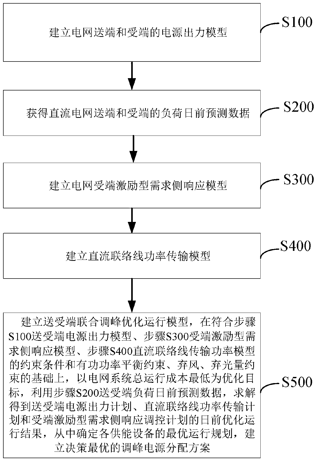
[0097] Such as figure 1 As shown, the combined peak-shaving optimization method of the sending and receiving ends of the DC power grid considering the constraints of the source, network and load described in this embodiment includes:

[0098] S100, establishing a power output model of the power grid sending end and receiving end;

[0099] S200. Obtain the day-ahead load forecast data at the sending end and the receiving end of the DC power grid;

[0100] S300. Establishing a power grid receiving-end incentive demand-side response model;

[0101] ...


PUM


Abstract

The invention discloses a dc grid transmitting and receiving end combined peak regulation optimization method considering source network load constraints, and can solve the technical problems that a 'linear' or 'reverse peak regulation' transmission plan often occurs in the prior art, which causes great difficulty in peak regulation, frequency modulation and operation mode arrangement of a receiving end grid. The method comprises the steps: firstly obtaining day-ahead output prediction data of a wind power plant and a photovoltaic power station; on the basis that a grid sending end power supply meets the requirement of local load power utilization, transmitting the generated surplus electric quantity to the grid receiving end through a high-voltage DC connecting line; taking the minimum total operation cost of a power grid system as an optimization target, taking the power balance constraint, the conventional generator set constraint, the wind curtailment and light curtailment constraint, the DC tie line constraint and the excitation type demand side response constraint as constraint conditions, establishing an optimization model, and obtaining operation power plans of each energysupply device which is accessed to DC, the high-voltage DC tie line and the excitation type demand side response of the receiving end. According to the invention, the energy consumption cost of a useris reduced, and the complementation and collaboration among various energy sources are improved.

Description

technical field [0001] The invention relates to the technical field of peak regulation in electric power systems, in particular to an optimization method for combined peak regulation at sending and receiving ends of a DC power grid considering the constraint of source, network and load. Background technique [0002] With the rapid development of new energy sources such as wind power and photovoltaic power generation, my country has gradually formed a power supply pattern of reverse distribution and centralized grid connection. Incorporate the scope to realize the optimal allocation of resources across the country. New energy power generation has the characteristics of randomness, intermittency, and volatility. There is a strong coupling relationship between the power generation level of new energy bases and DC transmission power. Currently, DC transmission power planning mainly considers system constraints and transmission volume agreements, and seldom considers the receiving...

Claims


Application Information

Patent Timeline
Patent Type & Authority Applications(China)
IPC IPC(8): H02J3/38H02J3/46
CPCH02J3/46Y02E10/76
Inventor 王磊张家敏
Owner 中科海奥(黄山)储能科技有限公司
Why Eureka
Try Eureka