
A fpga-based array channel correction method

A channel correction and array technology, applied in the radar field, can solve problems such as lack of correction and divergence of adaptive iterative algorithms, achieve consistent amplitude and phase responses, overcome the cumbersome calculation of system correction coefficients, and have rich FPGA interfaces

Active Publication Date: 2022-04-01
中国人民解放军91550部队
View PDF7 Cites 0 Cited by
  • Summary
  • Abstract
  • Description
  • Claims
  • Application Information

AI Technical Summary

Problems solved by technology

It requires that the reference signal data obtained by the direct coupling of the transmitting antenna channel and the sampling data passing through the radio frequency channels of the transmitting antenna are strictly synchronized, otherwise the adaptive iterative algorithm will diverge and the purpose of correction will not be achieved.

Method used


Image

  • A fpga-based array channel correction method
  • A fpga-based array channel correction method
  • A fpga-based array channel correction method

Examples


Embodiment

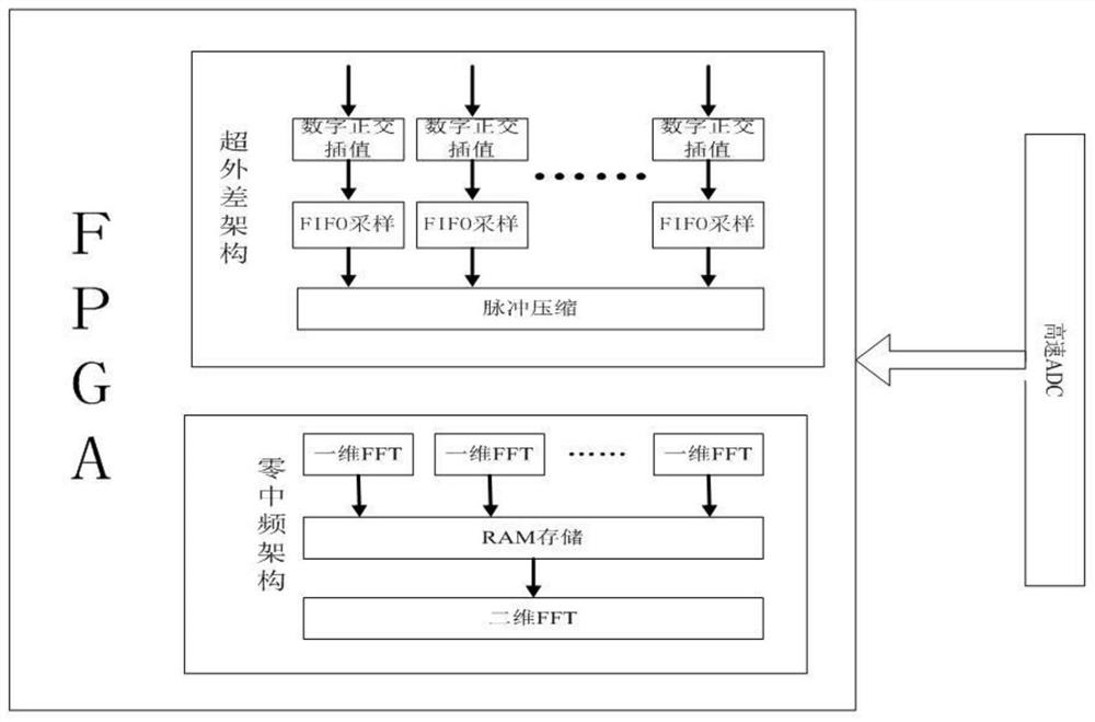
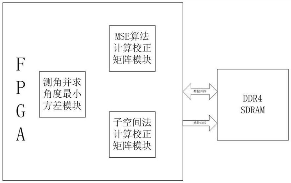
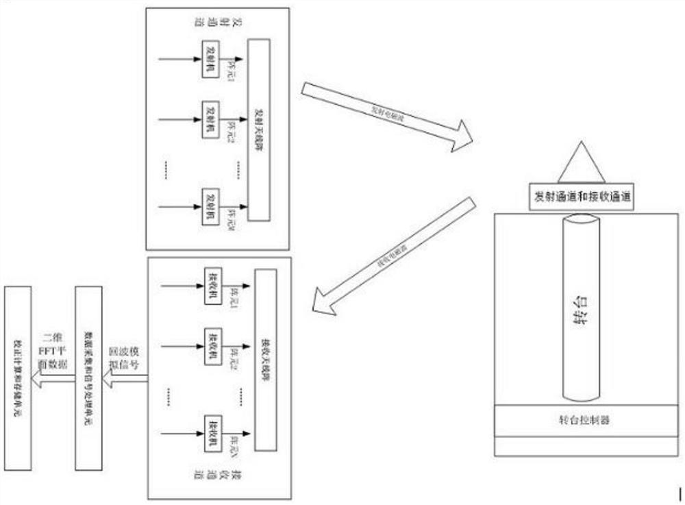
[0053] Example: such as figure 1 As shown, an FPGA-based array channel correction system includes a transmitting channel, a receiving channel, a corner reflector or a target simulator, a rotation control unit, a data acquisition and signal processing unit, a correction calculation and storage unit, and the transmitting channel includes a multi-channel The transmitter, the transmitting antenna array, the receiving channel includes a multi-channel receiver, the rotary control unit includes a turntable and a high-precision turntable controller, the transmitting channel and the receiving channel are fixed on the rotary control unit, and the corner reflector or target simulator is fixed At the other end of the darkroom, the distance between the rotary control unit and the corner reflector meets the far-field conditions, and the output end of the receiving channel is connected to the data acquisition and signal processing unit, which is composed of an analog-to-digital converter ADC ...


PUM


Abstract

The present invention relates to the field of radar technology, specifically, an FPGA-based array channel calibration system and method, wherein the transmitting channel includes a multi-channel transmitter and a transmitting antenna array, the receiving channel includes a multi-channel receiver, and the rotation control unit includes A turntable and a high-precision turntable controller, the transmitting channel and receiving channel are fixed on the rotating control unit, the corner reflector or target simulator is fixed at the other end of the darkroom, the distance between the rotating control unit and the corner reflector is in line with Field conditions, the output end of the receiving channel is connected to the data acquisition and signal processing unit, the data acquisition and signal processing unit is composed of an analog-to-digital converter ADC and a field programmable gate array FPGA, and the correction calculation and storage unit is composed of an FPGA and a synchronous dynamic read-only memory The SDRAM is formed, and the correction calculation and storage unit is connected with the data acquisition and signal processing unit through the bus.

Description

technical field [0001] The present invention relates to the technical field of radar, specifically, an FPGA-based array channel correction system and method, which is used to correct the channel error in a multi-antenna multi-channel array or a multiple-input multiple-receive (MIMO) radar system and method, which can be used To solve the problem of inconsistent amplitude and phase response of multiple antennas and multiple transceiver channels in an array or MIMO system. Background technique [0002] At present, in the field of radar array calibration technology at home and abroad, there are two main methods for correcting the amplitude and phase errors of the transmitting or receiving system: injection reference correction and blind correction. [0003] Ye Siqing and others disclosed a reference injection correction method in their patent application document "A Method and System for Channel Calibration" (publication number CN100514947C, application number 200510135012.6, f...

Claims


Application Information

Patent Timeline
Patent Type & Authority Patents(China)
IPC IPC(8): H04B17/12H04B17/21H04B7/0413
CPCH04B17/12H04B17/21H04B7/0413
Inventor 李增有王琼刘嗣勤韦俞峰刘秋辉张建立卢长海李中伟孙玮琢陈宏烨宋磊
Owner 中国人民解放军91550部队
Learn More