
Installation and method for liquefying natural gas

A technology for natural gas and liquefied gas, applied in the field of natural gas liquefaction, which can solve the problems of complex control of pre-cooling circuit and difficulty in predicting the function change of gas cooling circuit in productivity.

Active Publication Date: 2019-11-05
诺瓦泰克公共股份公司
View PDF14 Cites 0 Cited by
  • Summary
  • Abstract
  • Description
  • Claims
  • Application Information

AI Technical Summary

Problems solved by technology

[0019] A disadvantage of the method and device of RU 2538192 C1 is the complex control of the precooling circuit
The presence of a liquid phase downstream of each compression stage makes it difficult to predict functional changes in the main gas cooling circuit with changes in any parameters such as air temperature, refrigerant compression ratio, reduction / increase in production rate

Method used


Image

  • Installation and method for liquefying natural gas

Examples


Embodiment Construction

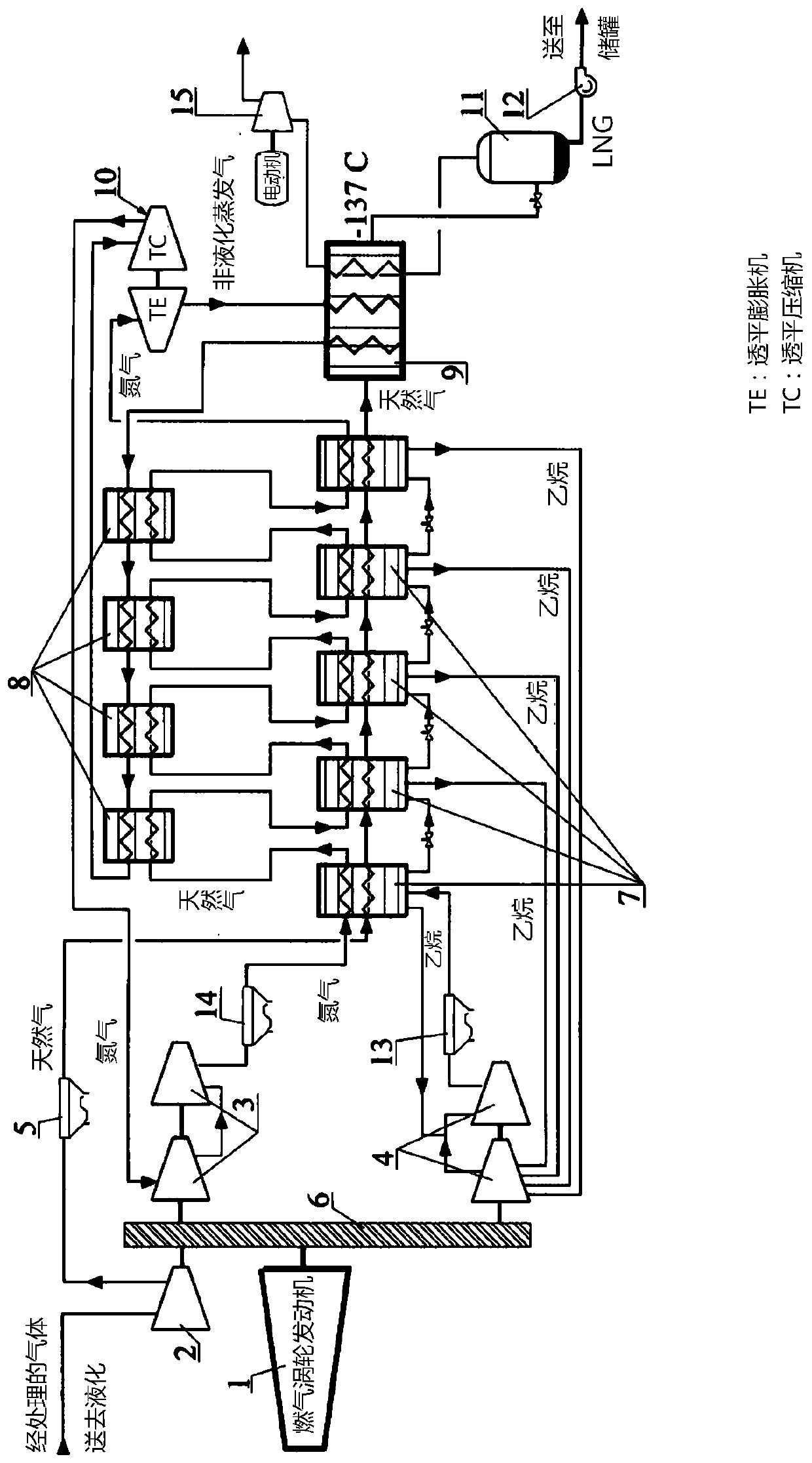
[0038] The natural gas liquefaction pipeline includes a natural gas compressor 2 , an air cooler 5 , an ethane evaporator 7 , a closed subcooling heat exchanger 9 (for example, multi-thread) and a separator 10 connected in series.

[0039] The ethane loop comprises at least one ethane compressor 4 connected in series ( figure 1 shows two compressors 4) connected in series, an air cooler 13 and said evaporator 7, the outlet of which is connected to the inlet of at least one compressor 4. As shown, the outlet of the first evaporator 7 is connected to the inlet of the second compressor 4 , while the outlets of the remaining evaporators 7 are connected to the first compressor 4 in stages.

[0040] The nitrogen loop includes at least one nitrogen compressor 3 ( figure 1 Two compressors 3) connected in series, the air cooler 14, the ethane evaporator 7 (with the nitrogen-nitrogen heat exchanger 8 connected therebetween), the turboexpander of the expander-compressor unit 10 are shown ...


PUM


Abstract

The invention relates to technology for liquefying natural gas. A method for liquefying natural gas consists in that processed natural gas is pre-cooled, ethane is separated off, the gas being liquefied is supercooled with the use of cooled nitrogen as a refrigerant, the pressure of the gas being liquefied is reduced, non-liquefied gas is separated off and liquefied natural gas is discharged. Furthermore, prior to the pre-cooling, the natural gas is compressed, ethane is separated off in a process of multi-stage pre-cooling of the gas being liquefied, with simultaneous evaporation of ethane with the use of cooled ethane as a refrigerant. The ethane produced during the evaporation is compressed, condensed and used as a refrigerant during the cooling of the gas being liquefied and of the nitrogen, wherein the nitrogen is compressed, cooled, expanded and fed to the stage of supercooling of the natural gas. The invention simplifies the technological process of liquefying natural gas.

Description

technical field [0001] The present invention relates to natural gas liquefaction technology for its further transport by river or sea and subsequent regasification. Background technique [0002] There are a number of methods to liquefy natural gas, mainly based on heat removal with external refrigerants, of which C3MR, Philips Cascade, Shell DMR and Linde MFCP liquefaction technologies are used in arctic climates. [0003] C3MR technology is employed at the NOVATEK, JSC plant on the Yamal peninsula in Sabetta, the Yamal liquefied natural gas (LNG) project. [0004] Initially, the C3MR process (GB 1291467A, 04.10.1972) was developed by Air Products for an LNG plant in Brunei. The technology is based on a natural gas cooling sequence: first, a separate propane-based vapor compression cycle is used in three heat exchangers, followed by a refrigerant mixture-based cycle in a two-zone multi-stage heat exchanger, which can also be used in two heat exchangers Propane circulation ...

Claims


Application Information

Patent Timeline
Patent Type & Authority Applications(China)
IPC IPC(8): F25J1/02
CPCF25J1/0022F25J1/004F25J1/005F25J1/0052F25J1/0072F25J1/0085F25J1/0205F25J1/025F25J1/0265F25J1/0283F25J1/0288F25J1/029F25J2220/64F25J2230/20F25J2230/30F25J1/02F25J1/0207F25J1/0208F25J2270/08F25J2270/12F25J2270/14F25J2270/42
Inventor R·M·米尼古罗夫S·V·鲁登科O·E·瓦辛D·N·格里茨辛E·I·索伯列夫
Owner 诺瓦泰克公共股份公司
Learn More