Method and device for the two-dimensional imaging of a positron emitter distribution of weakly positron-absorbing objects

A technology of positron emission and electron emitter, applied in radiation measurement, X/γ/cosmic radiation measurement, instruments, etc., can solve the systematic underestimation of density distribution, insufficient distribution characterization, and difficulty in designing positron emitter density Distributed positron escape probability and other issues to achieve the effect of improved quantification

Pending Publication Date: 2019-11-05
KERNFORSCHUNGSANLAGE JUELICH GMBH
View PDF8 Cites 0 Cited by
  • Summary
  • Abstract
  • Description
  • Claims
  • Application Information

AI Technical Summary

Problems solved by technology

Escaping positrons can no longer be directly detected by the PET method, so here, quantification in principle leads to a systematic underestimation of the true positron emitter density distribution
It is difficult to devise an estimate of the escape probability of positrons for correcting the positron emitter density distributi

Method used


Image

  • Method and device for the two-dimensional imaging of a positron emitter distribution of weakly positron-absorbing objects
  • Method and device for the two-dimensional imaging of a positron emitter distribution of weakly positron-absorbing objects

Examples


Embodiment Construction

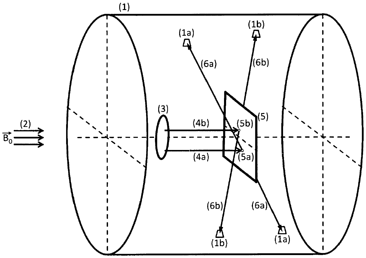
[0057] figure 1 A device for carrying out the method according to the invention is shown in . In the figure, reference numeral 1 denotes a PET detector system with PET photodetectors 1a, 1b. On the left, the magnetic field B 0 Shown with the reference numeral 2, it extends into the PET detector system 1 . The object to be examined 3 is located in the magnetic field 2 . The emitted positrons 4 a, 4 b depart from the object to be examined 3 , and the emitted positrons strike the positron absorption screen 5 . The impact points of the positrons on the positron absorbing screen 5 have the reference numerals 5a and 5b. Gamma quantum pairs 6a, 6b depart from impact points 5a, 5b, which strike the PET photodetectors 1a and 1b.

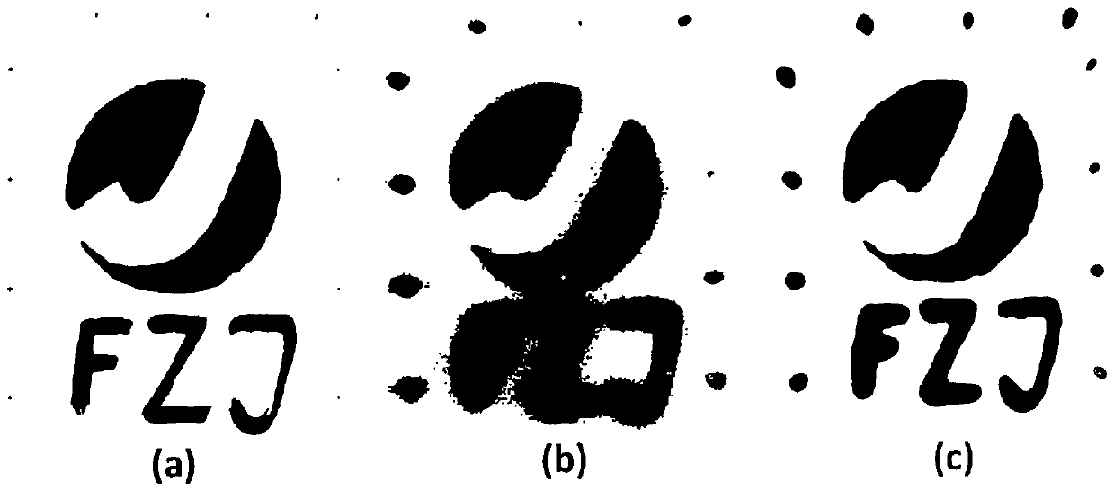
[0058] figure 2 The 2D images on the positron density distribution are shown in subfigures a), b) and c).

[0059] In subfigure a), the image is shown, which is not only marked in color but also on its entire face marked with color 18 The F symbols a...


PUM

PropertyMeasurementUnit
Thicknessaaaaaaaaaa

Abstract

The invention relates to a method and a device for the two-dimensional imaging of a positron emitter distribution of weakly positron-absorbing objects. According to the invention, the method is characterized in that the object to be examined which contains the positron emitter is positioned in a magnetic field, and the positrons leaving the object to be examined follow the curve of the magnetic field and strike a positron absorber which is likewise positioned in the magnetic field and which, upon interacting with the positrons, allows the position where the positrons struck the positron absorber to be located. For this purpose, the object to be examined which contains the positron emitter and a positron absorber are placed in a magnetic field such that the positrons follow the curve of themagnetic field and strike the positron absorber at a position. The information obtained in this manner regarding the position where the positrons struck the positron absorber is used to image the positron emitter distribution in the object to be examined.

Description

technical field [0001] The present invention relates to a method and apparatus for two-dimensional imaging of the positron emitter distribution of a weakly positron absorbing object. Background technique [0002] To date, the state of the art is represented by positron emission tomography [PET] as a general three-dimensional imaging method [1], which can be used in particular to quantify biological dynamic metabolic processes (in vivo). Diverse fields of application can be found, for example, in preclinical research, human medicine, neuroscience and in the study of metabolic processes in plants. For this purpose, there are a large number of commercial and non-commercial PET scanners of various constructions, depending on the field of application. As a recent development, it is also applied to MR / PET hybrid detector systems [2] in order to achieve: Metabolism obtained by means of PET at a lower spatial resolution (usually 2-5 mm) determined by the physical technique Optimal...

Claims


Application Information

Patent Timeline
IPC IPC(8): G01T1/29
CPCG01T1/2985
Inventor J.舍因斯
Owner KERNFORSCHUNGSANLAGE JUELICH GMBH
Why Eureka
Try Eureka