

Groove grinding wheel profile automatic detection and regulation trimming device and method
A technology of automatic detection and dressing device, which is used in abrasive surface adjustment devices, parts of grinding machine tools, control of workpiece feed movement, etc. problems, to achieve the effect of improving product quality and high precision
- Summary
- Abstract
- Description
- Claims
- Application Information
AI Technical Summary
Problems solved by technology
Method used
Image

Examples
Embodiment 1
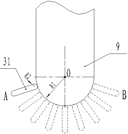
[0057] Dressing of CBN grinding wheel for bearing groove grinding with single-segment arc profile, such as figure 2 shown.
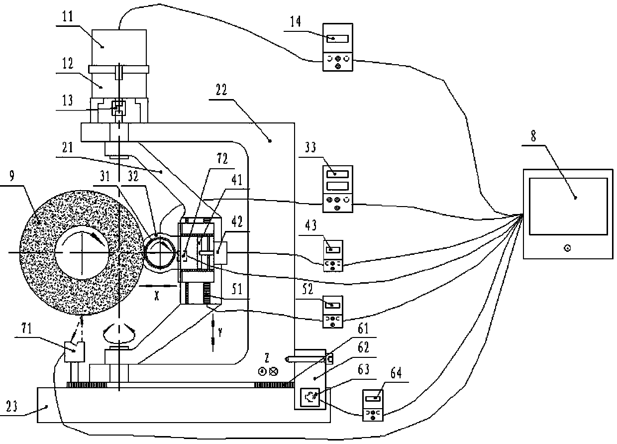
[0058] 1. In the analysis controller 8, parameters such as the outer diameter of the grinding wheel 9 to be trimmed, the width, the grain size, and the radius of curvature of the dressing profile are input, and parameters such as the outer diameter of the diamond roller 31, the arc radius of the tool tip, and the speed of rotation of the swing dressing frame 21 , rotation angle, the speed of the diamond roller 31 and other trimming process parameters;
[0059] 2. Start the matching dressing program, and the device will automatically find the initialization position suitable for the grinding wheel 9 to be dressed:
[0060] 2.1 The analysis controller 8 controls the swing driving mechanism to adjust the swing dressing frame 21 to rotate to a position where the axis of the diamond roller 31 is parallel to the axis of the grinding wheel 9 to be dressed, ...
Embodiment 2
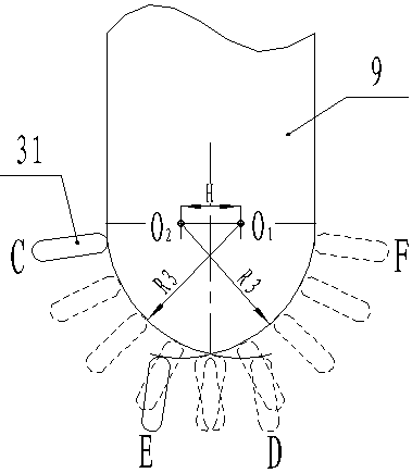
[0068] Dressing of bearing channel grinding CBN grinding wheel with peach-shaped groove profile, such as image 3 shown.
[0069]1. In the analysis controller 8, parameters such as the outer diameter of the grinding wheel 9 to be dressed, width, grain size, radius of curvature of the dressing profile, groove center distance, etc., and parameters such as the outer diameter of the diamond roller 31 and the radius of the arc of the tool tip are input, and the dressing frame is swung. 21 Dressing process parameters such as rotation speed, rotation angle, and the rotating speed of diamond roller 31.
[0070] 2. Start the matching trimming program, the same as in Embodiment 1, the device automatically finds the initialization position adapted to the grinding wheel 9 to be trimmed, that is: the swing trimming frame 21 rotates to a position where the axis of the diamond roller 31 is parallel to the axis of the grinding wheel 9 to be trimmed, as a rotary swing Angle 0° position; the...
Embodiment 3
[0075] Dressing of CBN grinding wheel for bearing channel grinding with multi-arc complex profile, such as Figure 4 shown.
[0076] 1. In the analysis controller 8, parameters such as the outer diameter of the grinding wheel 9 to be dressed, width, grain size, radius of curvature of the dressing profile, groove center distance, etc., and parameters such as the outer diameter of the diamond roller 31 and the radius of the arc of the tool tip are input, and the dressing frame is swung. 21 Dressing process parameters such as rotation speed, rotation angle, and the rotation speed of diamond roller 31;
[0077] 2. Start the matching trimming program, the same as in Embodiment 1, the device automatically finds the initialization position adapted to the grinding wheel 9 to be trimmed, that is: the swing trimming frame 21 rotates to a position where the axis of the diamond roller 31 is parallel to the axis of the grinding wheel 9 to be trimmed, as a rotary swing Angle 0° position;...
PUM
 Abstract
Description
Claims
Application Information