

Automobile and hybrid power system
A hybrid system and clutch technology, applied in hybrid vehicles, power units, pneumatic power units, etc., can solve problems such as large energy loss
- Summary
- Abstract
- Description
- Claims
- Application Information
AI Technical Summary
Problems solved by technology
Method used
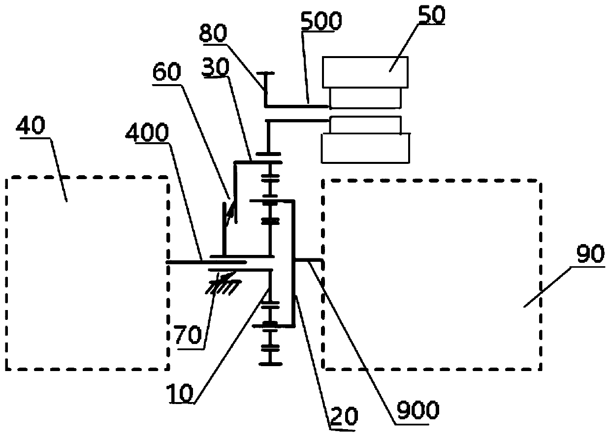
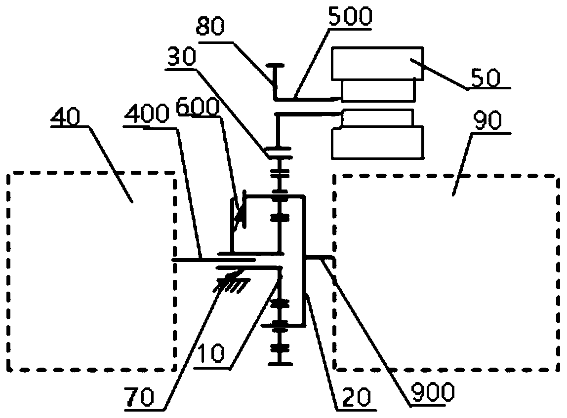
Image

Examples
Embodiment Construction
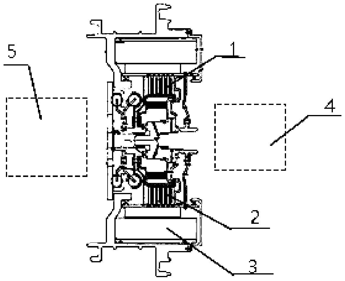
[0032] It can be known from the background technology that the current P2 mode hybrid power system has a large energy loss.
[0033] Please refer to figure 1 , figure 1 It is a partial structure diagram of a hybrid power system.
[0034] As shown in the figure, the hybrid power system includes a motor, a first clutch 1, a second clutch 2, the left end is connected to the engine 5, and the right end is connected to the gearbox 4. In the hybrid power output mode, because the engine 5 and the motor 3 share the same output shaft, the engine 5 and the motor 3 have the same speed. Because the engine 5 and the motor 3 operate in different speed ranges, the engine 5 and the motor 3 share the same output The shaft also restricts that the speeds of the engine 5 and the motor 3 must be equal. This leads to the fact that when the speed of the output shaft meets the speed range of the engine 5 to operate efficiently, the motor 3 cannot operate efficiently. Similarly, when the output shaft When...
PUM
 Abstract
Description
Claims
Application Information