Large-span tie bar arch bridge approach bridge jacking system and jacking construction method

A tie-arch bridge and long-span technology, applied in the field of jacking system and jacking construction of large-span tied-arch bridge approach, can solve the problems of difficult control of the jacking construction process, heavy jacking weight, complicated process, etc.

Pending Publication Date: 2019-11-08
NO 1 ENG LIMITED OF CR20G
View PDF0 Cites 2 Cited by
  • Summary
  • Abstract
  • Description
  • Claims
  • Application Information

AI Technical Summary

Problems solved by technology

When jacking up the approach bridge, there are the following construction problems: first, the number of spans of the approach bridge is large and the jacking weight is heavy, the risk points are scattered, and the overall jacking construction process is difficult to control; second, during the jacking process, the upper structure of the bridge is in suspension There are great potential safety hazards, and effective measures must be taken to resolve the above risks to ensure the safety of bridges and construction personnel; third, the jacking height is relatively high, with a jacking height of 2.16m, and there are many temporary pads

Method used


Image

  • Large-span tie bar arch bridge approach bridge jacking system and jacking construction method
  • Large-span tie bar arch bridge approach bridge jacking system and jacking construction method
  • Large-span tie bar arch bridge approach bridge jacking system and jacking construction method

Examples


Embodiment Construction

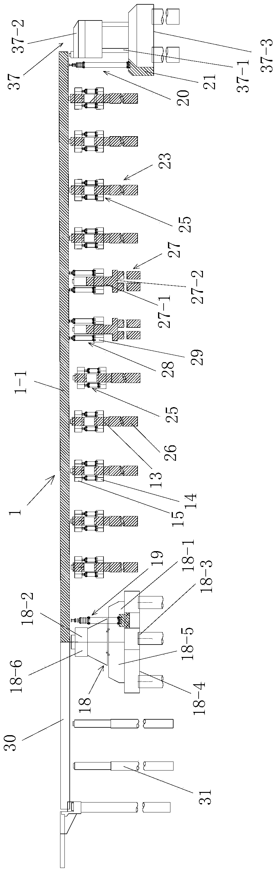
[0115] Such as figure 1 A long-span tied arch bridge approach jacking system shown includes two left and right symmetrically arranged approach bridge main beam jacking devices for vertically lifting the main beam 1 of the approach bridge to be lifted; the main beam 1 of the approach bridge to be jacked It is the main girder of the approach bridge of a long-span tied arch bridge; the main girder 1 of the approach bridge to be lifted is arranged horizontally and includes two longitudinal main girders 1-1 arranged symmetrically on the left and right sides, and the two longitudinal main girders 1-1 They are arranged along the longitudinal direction of the bridge; each of the main beam jacking devices of the approach bridge is supported directly below one of the longitudinal main beams 1-1, and each of the main beam jacking devices of the approach bridge includes a hydraulic jacking device on the abutment side 19 and a pier side hydraulic jacking device 20 arranged symmetrically wi...


PUM


Abstract

The invention discloses a large-span tie bar arch bridge approach bridge jacking system and jacking construction method. The system comprises a left approach bridge main beam jacking device and a right approach bridge main beam jacking device, wherein each of the approach bridge main beam jacking devices comprises an abutment-side hydraulic jacking device and a pier-side hydraulic jacking device,and each of both the abutment-side hydraulic jacking device and the pier-side hydraulic jacking device of each approach bridge main beam jacking device is an approach bridge beam end jacking device; and each of the approach bridge beam end jacking devices comprises a transverse distribution beam, a plurality of vertical jacking devices and a plurality of auxiliary supporting structures. The jacking construction method comprises the following steps of 1, mounting the jacking devices; 2, carrying out jacking; 3, increasing height of an approach bridge lower structure in a jointing way; and 4, removing the jacking devices. The large-span tie bar arch bridge approach bridge jacking system and jacking construction method have the advantages of reasonable structure design, simple and convenientconstruction and good use effect; the two left and right symmetrically-arranged approach bridge main beam jacking devices are adopted to carry out vertical jacking on a to-be-jacked approach bridge main beam, the vertical jacking devices and the auxiliary supporting structures are adopted in each approach bridge main beam jacking device to cooperate together to carry out jacking, and meanwhile theadopted temporary supporting structures have good bearing effect and good supporting stability, thus ensuring that the jacking process of the approach bridge main beam is stable and reliable.

Description

technical field [0001] The invention belongs to the technical field of bridge jacking construction, and in particular relates to a jacking system and a jacking construction method for a long-span tied arch bridge approach bridge. Background technique [0002] Bridge jacking construction (also known as bridge jacking technology) refers to the adoption of the overall hydraulic synchronous lifting scheme, that is, using the original cast-in-place piles to bear the load, without destroying the original bridge deck pavement, railings, sidewalks, and beams and slabs. Connections, etc., first use the hydraulic jacking device to withstand the overall structure of the bridge, then cut off the columns under each pier and platform cap beam, and then operate the hydraulic jacking device to raise the bridge as a whole to the design height, and finally connect the long column steel bars Formwork pouring of the second stage concrete. The bridge superstructure refers to the general term fo...

Claims


Application Information

Patent Timeline
IPC IPC(8): E01D4/00E01D21/00
CPCE01D4/00E01D21/00
Inventor 赵罡颉张记军杜越梁之海李金宝朱书洁汪洋严朝锋王永丽
Owner NO 1 ENG LIMITED OF CR20G
Why Eureka
Try Eureka