Vibration table-based material damping coefficient measurement method and device

A material damping and measuring device technology, which is applied in the direction of measuring devices, analyzing materials, and adopting mechanical devices, etc., can solve problems such as unrealistic measurement systems, large measurement errors, and sensor signal distortion, so as to simplify measurement design schemes and improve analysis and processing speed, reduced clamping requirements

Active Publication Date: 2019-11-08
LOW SPEED AERODYNAMIC INST OF CHINESE AERODYNAMIC RES & DEV CENT
View PDF7 Cites 3 Cited by
  • Summary
  • Abstract
  • Description
  • Claims
  • Application Information

AI Technical Summary

Problems solved by technology

The first is to test the damping coefficient by hydraulic testing machine and electronic universal testing machine, but it is only suitable for the static measurement of the damping coefficient of the material with large displacement; the second is to use the fatigue testing machine with high frequency tension and compression, but it is only applicable It is mainly used in the dynamic test of the damping coefficient of large displacement damping materials such as rubber; the third method is to measure the material damping coefficient by using the free decay method of the hammer, but the measurement efficiency of this method is low and the measurement error is large; The vibrator is used in the measurement of other sensors, mainly using the cantilever beam method, the free beam method and the impedance method to measure the damping coefficient, but this type of method is not suitable for measuring the damping coeffi

Method used


Image

  • Vibration table-based material damping coefficient measurement method and device
  • Vibration table-based material damping coefficient measurement method and device
  • Vibration table-based material damping coefficient measurement method and device

Examples


Example Embodiment

[0036] All features disclosed in this specification, or steps in all methods or processes disclosed, may be combined in any manner, except for mutually exclusive features and / or steps.

[0037] Any feature disclosed in this specification (including any appended claims, abstract and drawings), unless expressly stated otherwise, may be replaced by alternative features which are equivalent or serve a similar purpose. That is, unless expressly stated otherwise, each feature is one example only of a series of equivalent or similar features.

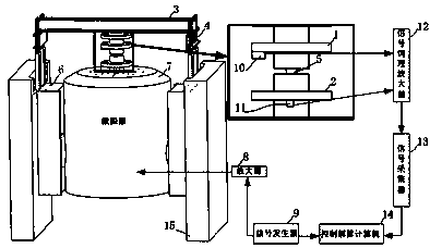
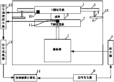
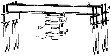
[0038] like figure 1 , figure 2 , image 3 As shown, the measuring device of this embodiment includes two exciter foundations 6, an exciter 7, a beam 3 arranged above the exciter, an upper platen 1 and a lower platen 1 connected between the beam 3 and the exciter 7. The pressing plate 2 and the tested object 5 between the upper and lower pressing plates, the laser displacement sensor 10 installed on the upper pressing plate and the pressur...


PUM


Abstract

The invention discloses a vibration table-based material damping coefficient measurement method and device, and relates to the field of material measurement. In order to achieve the purpose, a signalgenerator is utilized for generating steady-state frequency voltage, so that the vibration table has an exciting force, and the exciting force makes the material generate a dynamic displacement response curve under different loading forces, the material damping coefficient is worked out according to exciting signal information of a signal generator and dynamic response information of the material,and meanwhile by means of a designed measurement device, adjustment and pressure loading are facilitated. The device comprises an exciter, a beam applying pressure and a test piece clamped between anupper fixing pressing plate and a lower fixing pressing plate, a laser displacement sensor is installed on the upper fixing pressing plate; a pressure sensor is installed on the lower fixing pressingplate, the signal collected through a signal collector is fed back to a computer, and the damping coefficient of the material is resolved. Accordingly, not only is the measurement damping coefficientaccurate and the measurement stability is high, but also clamping is easy, the pressure is loaded conveniently, and the method and device are applicable to test analysis of various damping materials.

Description

technical field [0001] The invention relates to the field of material damping coefficient measurement, in particular to a method and device for measuring the damping coefficient of a nonlinear damping material based on a vibrating table in various frequency ranges and materials under different loading forces. Background technique [0002] Damping materials have certain deformation and energy dissipation characteristics. The determination of the damping coefficient η is an important basis for whether the damping and noise reduction performance of the damping material is up to standard. It is widely used in the fields of automobile manufacturing, aerospace manufacturing, and large-scale equipment manufacturing. Vibration and noise generated by noise excitation. The determination of the damping coefficient is directly related to the vibration isolation performance of the vibration-isolated equipment, but the damping coefficient cannot be directly measured by the equipment, and ...

Claims


Application Information

Patent Timeline
IPC IPC(8): G01N19/00
CPCG01N19/00
Inventor 武亮亮陶瑜姜德龙张德久
Owner LOW SPEED AERODYNAMIC INST OF CHINESE AERODYNAMIC RES & DEV CENT
Why Eureka
Try Eureka