Camera, imu and laser radar combined robot positioning method

A robot positioning and laser radar technology, which is applied in the directions of instruments, electromagnetic wave re-radiation, image data processing, etc., can solve the problems of low accuracy and stability, point cloud matching, etc., and achieve the effect of eliminating cumulative errors

Active Publication Date: 2019-11-08
SICHUAN UNIV
View PDF4 Cites 22 Cited by
  • Summary
  • Abstract
  • Description
  • Claims
  • Application Information

AI Technical Summary

Problems solved by technology

[0003] Most of the existing robot solutions are based on cameras or low-beam laser radars. Camera-based solutions will bring problems of low accuracy and stability, and purely based on laser radars will also bring problems that point cloud matching cannot be performed well.

Method used


Image

  • Camera, imu and laser radar combined robot positioning method
  • Camera, imu and laser radar combined robot positioning method
  • Camera, imu and laser radar combined robot positioning method

Examples


Embodiment Construction

[0031] The present invention will be further described below in conjunction with accompanying drawing:

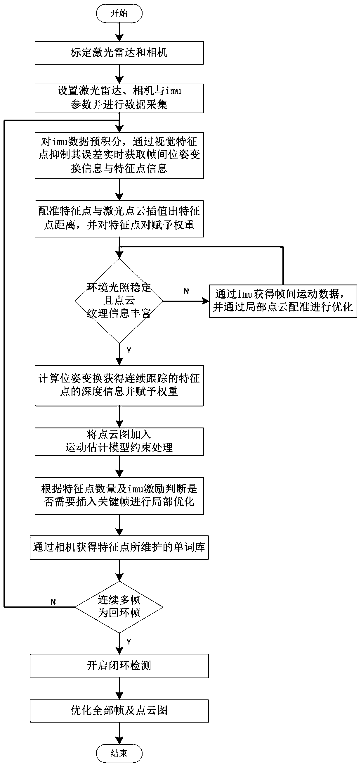
[0032] Such as figure 1 As shown, the purpose of the present invention is to provide a robot positioning method combining camera, imu and laser radar in order to solve the above problems, including the following steps:

[0033] S1: Calibrate the lidar and camera so that the laser points and pixels can achieve pixel-level accuracy;

[0034] S2: Set the laser radar scanning frequency, scanning angle, camera refraction rate and imu frequency and perform data collection;

[0035] S3: Pre-integrate the imu data, and suppress its error through visual feature points, and obtain inter-frame pose transformation information and feature point information in real time;

[0036] S4: Register feature points and laser point cloud, select feature point ray to be located in the feature point pair of laser point cloud curvature smaller area, interpolate out feature point distance, and assi...


PUM


Abstract

The invention discloses a camera, imu and laser radar combined robot positioning method, comprising the steps: maintaining the more accurate depth of a surrounding environment through the camera and the laser radar, and constructing a speedometer through the continuous tracking of feature points. According to the camera, imu and laser radar combined robot positioning method, the advantages of thecamera, the imu and the laser radar can be combined; an accurate and dense point cloud map is established for the robot to perform path planning; the precision of the interframe odometer is improved through tight coupling of the camera and the laser radar; high robustness is achieved; through a point cloud map maintained by laser and a camera in real time, local optimization of the odometer is carried out in laser scanning; and a loop is judged through word information provided by a camera and imu data, and closed-loop optimization is achieved on a point cloud map provided by vision and laserjointly.

Description

technical field [0001] The invention relates to the technical field of robot positioning, in particular to a robot positioning method combining a camera, an IMU and a laser radar. Background technique [0002] As technologies such as computing power and sensors continue to increase, the functions of outdoor patrol and security robots are also becoming more and more, and at the same time, the mixed use of multi-sensor data is becoming more and more diverse. The robot is no longer limited to the use of a single sensor, but can obtain more accurate environment and pose information through the cooperation of multi-sensor data. As an important means of robot positioning, the mutual use of multi-sensor data requires strong computing power, and the development of computers now provides a good foundation for this condition. [0003] Most of the existing robot solutions are based on cameras or low-beam laser radars. Camera-based solutions will bring problems of low accuracy and stab...

Claims


Application Information

Patent Timeline
Patent Type & Authority Applications(China)
IPC IPC(8): G06T7/73G06T7/33G06T7/246G06T7/521G01S17/02G01S17/89G01S17/93
CPCG01S17/89G01S17/93G06T7/246G06T7/33G06T7/521G06T7/73G06T2207/10028G06T2207/10044
Inventor 张轶黄瑞
Owner SICHUAN UNIV
Why Eureka
Try Eureka