Package structure and method for wound-type rotary transformer rotor

A resolver and packaging structure technology, applied in transformers, magnetic circuit shape/style/structure, inductance/transformer/magnet manufacturing, etc., can solve problems such as hidden dangers, unsightly appearance, and reduced reliability of resolvers, so as to improve the use of The effect of life and reliability, high mechanical strength and three-proof performance

Active Publication Date: 2019-11-08
苏州工业园区代尔塔电机技术有限公司
View PDF9 Cites 0 Cited by
  • Summary
  • Abstract
  • Description
  • Claims
  • Application Information

AI Technical Summary

Problems solved by technology

[0002] At present, the rotor of the wire-wound resolver is dipped in insulating varnish as a whole after the wire is wound, and then the wiring ends are wrapped with insulating material to protect the winding. The rotor is easily damaged, not only the appearance is not beautiful, but even after the whole rotor is dipped in paint, the insulating material binding the wire ends may be loose, which will cause hidden dangers and greatly reduce the reliability of the resolver or even fail

Method used


Image

  • Package structure and method for wound-type rotary transformer rotor
  • Package structure and method for wound-type rotary transformer rotor
  • Package structure and method for wound-type rotary transformer rotor

Examples


Embodiment Construction

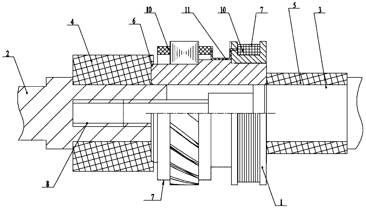
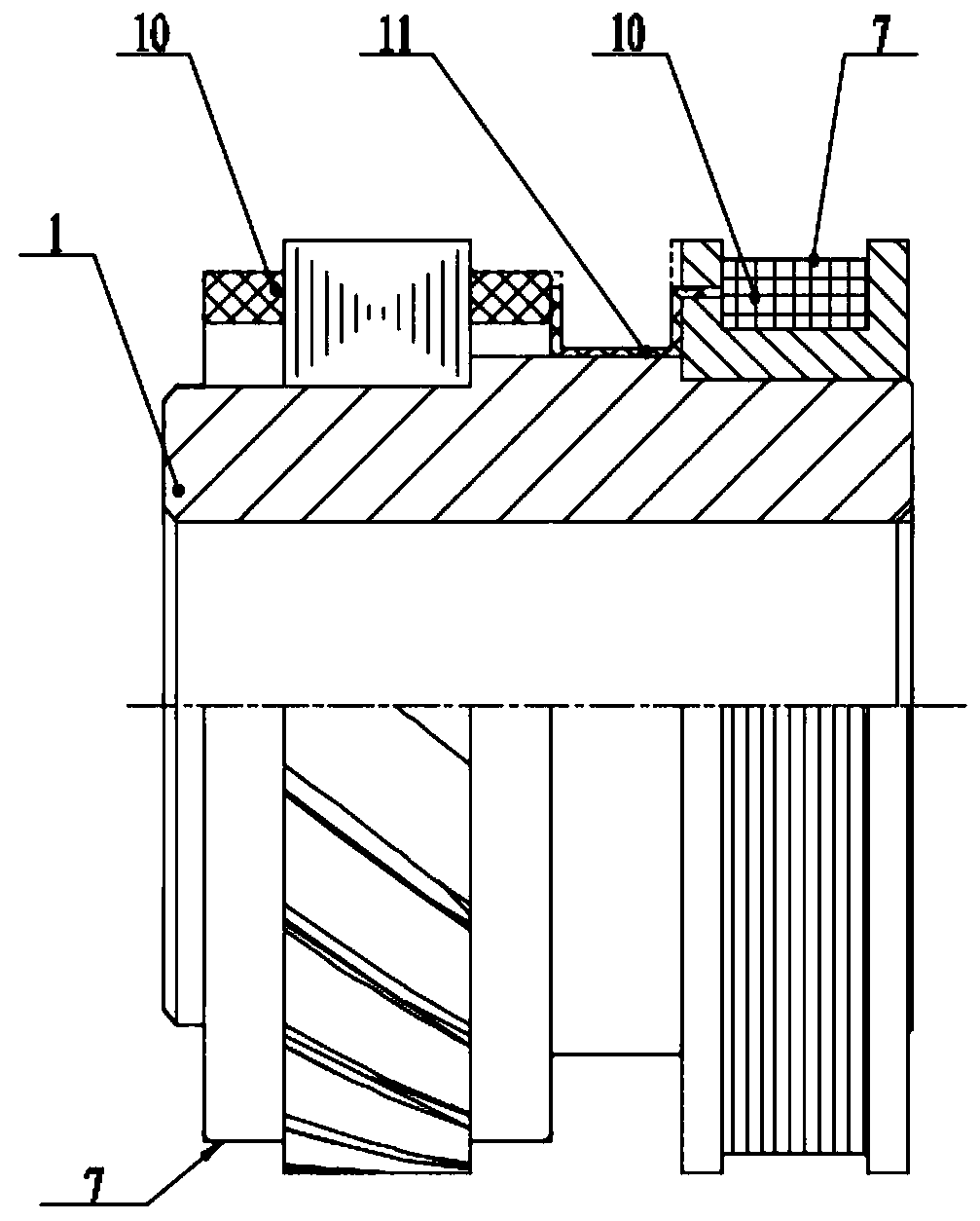
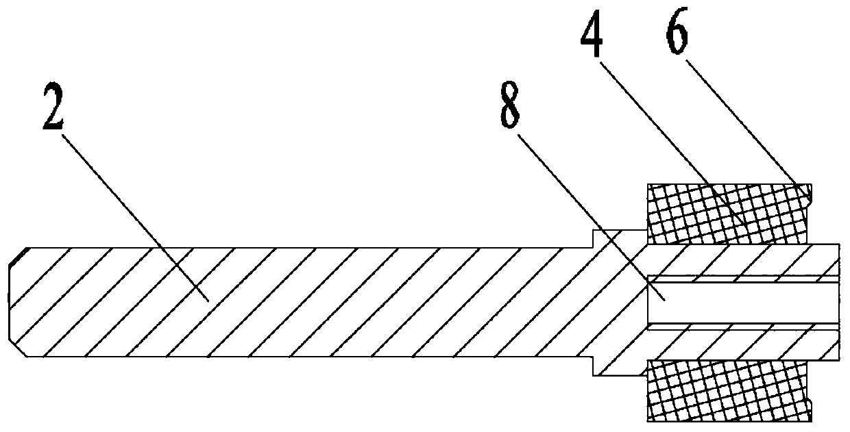
[0020] Such as Figure 1 ~ Figure 4 As shown, a packaging structure of a wound resolver rotor 1 according to the present invention includes a rotor 1, and also includes a first tooling 2 and a second tooling 3 opposite to each other. The first tooling 2 and the second tooling 3 are both It is cylindrical, and the opposite ends of the first tooling 2 and the second tooling 3 are respectively locked in the inner holes of the two ends of the rotor 1 by corresponding threads, and are locked on both ends of the rotor 1 through the first tooling 2 and the second tooling 3, so that Effectively protect the inner hole and end surface of the rotor 1 from being coated, prevent the paint from entering other places that do not need to be sprayed, and make the product beautiful; and the opposite ends of the first tooling 2 and the second tooling 3 The first locking piece 4 and the second locking piece 5 are connected with the corresponding tight fit respectively, and the ends of the first t...


PUM

PropertyMeasurementUnit
thicknessaaaaaaaaaa

Abstract

The invention provides a package structure and a method for a wound-type rotary transformer rotor, which can effectively protect a rotor winding and a wiring wire head under the conditions of the rotor landing, bumping and water entering, greatly improve the service life and the reliability of the rotary transformer and the appearance is beautiful and elegant. The package structure comprises a rotor and first and second tools which are oppositely arranged, the first and second tools are cylindrical shapes, the opposite end portions of the first and second tools are respectively correspondinglylocked in the inner holes of the two ends of the rotor, the opposite end portions of the first and second tools are respectively, correspondingly and tightly cooperated and connected with first and second locking pieces, the first and second tool end portions are respectively extruded to the corresponding end portions of the first and second locking pieces, the outer diameters of the first locking piece and the second locking piece are larger than the inner diameters of the inner holes of the rotor, the outer diameter of the first locking piece is larger than the outer diameter of the corresponding end portion of the rotor, the end face of the first locking piece of the rotor side is provided with the groove matching with the end portion of the rotor, and the outer round surfaces of the rotor are coated with epoxy layers.

Description

technical field [0001] The invention relates to the technical field of rotary transformers, in particular to a packaging structure and method for a winding type rotary transformer rotor. Background technique [0002] At present, the rotor of the wire-wound resolver is dipped in insulating varnish as a whole after the wire is wound, and then the wiring ends are wrapped with insulating material to protect the winding. The rotor is easily damaged, not only the appearance is not beautiful, but even after the whole rotor is dipped in paint, the insulating material binding the wire ends may be loose, which will cause hidden dangers and greatly reduce the reliability of the resolver or even fail. Contents of the invention [0003] In view of the above problems, the present invention provides a package structure and method for the rotor of a wire-wound resolver, which can still effectively protect the rotor windings and wiring ends under the circumstances of the rotor falling to t...

Claims


Application Information

Patent Timeline
Patent Type & Authority Applications(China)
IPC IPC(8): H01F38/18H01F27/28H01F41/02H02K24/00H02K1/22H02K15/02H02K15/12
CPCH01F27/28H01F38/18H01F41/005H01F41/02H02K1/22H02K15/02H02K15/12H02K24/00
Inventor 王洁郑彦波
Owner 苏州工业园区代尔塔电机技术有限公司
Why Eureka
Try Eureka