
Method and device for carbon reduction denitration of kiln flue gas

A denitration and flue gas technology, applied in the field of kiln flue gas, can solve the problems of waste of resources, failure to reach the temperature window, narrow effective temperature window, etc., and achieve the effects of no secondary pollution, improved production efficiency, and improved efficiency.

Active Publication Date: 2019-11-12
XIANGTAN UNIV
View PDF8 Cites 1 Cited by
  • Summary
  • Abstract
  • Description
  • Claims
  • Application Information

AI Technical Summary

Problems solved by technology

However, the denitrification efficiency is low, generally 50-60%. The biggest problem of this technology is that the effective temperature window of the reaction is narrow, and the temperature of the kiln flue gas is relatively low. window” (850°C-1100°C), which cannot meet the new national environmental protection requirements
[0004] At present, there is also a method for denitrifying the high-temperature (up to 600°C or more) flue gas containing nitrate in the kiln, which is directly discharged after denitrification. Due to the low denitrification efficiency, it will cause relatively large pollution when discharged, and because it is high-temperature flue gas, After denitrification, its calorific value is still very high. If it is discharged directly, it will cause a very large waste of resources.

Method used


Image

  • Method and device for carbon reduction denitration of kiln flue gas
  • Method and device for carbon reduction denitration of kiln flue gas
  • Method and device for carbon reduction denitration of kiln flue gas

Examples


Embodiment 1

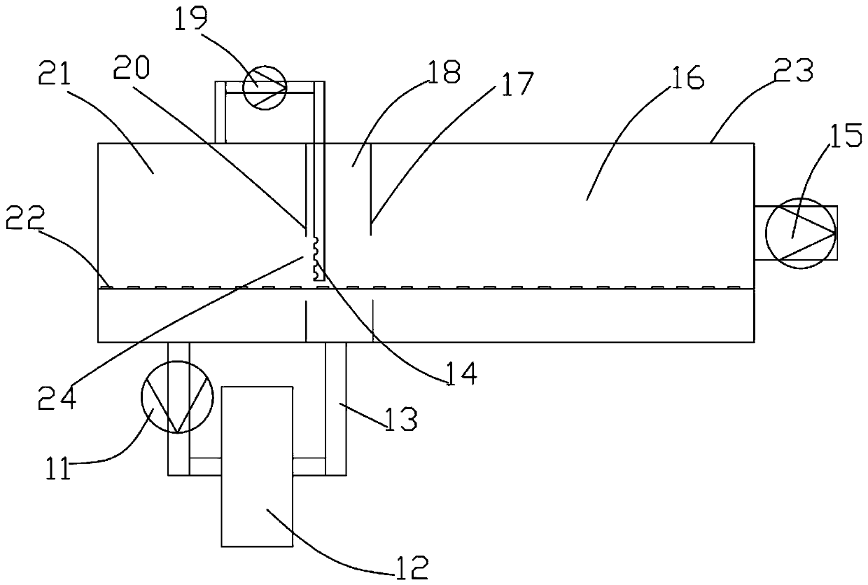
[0054] The simulated flue gas temperature is 700°C, and the NO concentration is 700mg / Nm 3 , SO 2 Concentration 0.5%, O 2 Concentration 1%, flue gas volume 100Nm 3 / h, the simulated flue gas in the induced draft chamber enters the carbon reduction denitrifier through the induced draft fan, and the operating pressure of the partition wall is 120pa. Continue to complete the drying and firing of the products in the kiln, and then discharge them through the exhaust fan to measure the NO x concentration.

Embodiment 2

[0056] The simulated flue gas temperature is 700°C and the NO concentration is 500mg / Nm 3 , SO 2 Concentration 1%, O 2 Concentration 1%, flue gas volume 100Nm 3 / h, the simulated flue gas in the induced draft chamber enters the carbon reduction denitrifier through the induced draft fan, and the operating pressure of the partition wall is 200pa. Continue to complete the drying and firing of the products in the kiln, and then discharge them through the exhaust fan to measure the NO x concentration.

Embodiment 3

[0058] The simulated flue gas temperature is 800°C and the NO concentration is 700mg / Nm 3 , SO 2 Concentration 0.5%, O 2 Concentration 1%, flue gas volume 100Nm 3 / h, the simulated flue gas in the induced draft chamber enters the carbon reduction denitrifier through the induced draft fan, and the operating pressure of the partition wall is 120pa. Continue to complete the drying and firing of the products in the kiln, and then discharge them through the exhaust fan to measure the NO x concentration.


PUM

PropertyMeasurementUnit
Pressureaaaaaaaaaa

Abstract

The invention discloses a method for carbon reduction denitration of kiln flue gas. The method includes the steps that to-be-denitrated high-temperature flue gas in an air induced chamber enters a carbon reduction denitrator for denitration under the action of an induced draft fan; the denitrated flue gas after denitration enters a separation chamber, one part of the denitrated flue gas in the separation chamber enters an air return chamber through an opening of an air return separation wall, and the other part of the denitrated flue gas enters the air induced chamber through the opening of anair induced separation wall; and air flows to the air induced chamber is formed by a flow guiding fan, and non-denitrated flue gas of the air induced chamber is blocked by the separation chamber. According to the method, NO<x> in the kiln flue gas can be removed, heat released in the denitration process is carried by the flue gas for product production, carbon reduction denitration is carried outby using the characteristic of the high temperature of the kiln flue gas, a C-NO<x> reaction is advantageously conducted, secondary pollution is basically avoided, and the denitration efficiency of the flue gas is greatly improved.

Description

technical field [0001] The invention relates to the technical field of kiln flue gas, in particular to a method for carbon reduction and denitrification of kiln flue gas and a device thereof. Background technique [0002] Industrial kiln is a device made of refractory materials for firing products. It is an essential facility in pottery molding and plays an important role in industrial production. However, environmental protection problems have always existed during operation, especially in my country's industrial furnaces such as cement kilns, glass kilns, ceramic kilns, etc., which produce extremely high emissions of nitrogen oxides (NOx) (1000-4000mg / Nm 3 ), which is 5-30 times the NOx emission concentration of thermal power plants, far exceeding the emission standards, and has become the third largest source of total NOx emissions after my country's thermal power industry and motor vehicles. NOx is one of the main pollution sources that cause atmospheric environmental p...

Claims


Application Information

Patent Timeline
IPC IPC(8): B01D53/56B01D53/81
CPCB01D53/56B01D53/81B01D2258/0283
Inventor 张俊丰符辉黄妍曹靖赵令葵
Owner XIANGTAN UNIV
Features
  • Generate Ideas
  • Intellectual Property
  • Life Sciences
  • Materials
  • Tech Scout
  • Unparalleled Data Quality
  • Higher Quality Content
  • 60% Fewer Hallucinations
Learn More