Cooking-free heat removal device for waste metal paint layer
A technology for scrap metal and paint layer, which is applied in grinding drive devices, metal processing equipment, cleaning methods and utensils, etc., can solve the problems of large air and dust pollution, low thermal efficiency, large thermal loss, etc., and achieve the effect of complete separation
- Summary
- Abstract
- Description
- Claims
- Application Information
AI Technical Summary
Problems solved by technology
Method used
Image

Examples
Embodiment 1
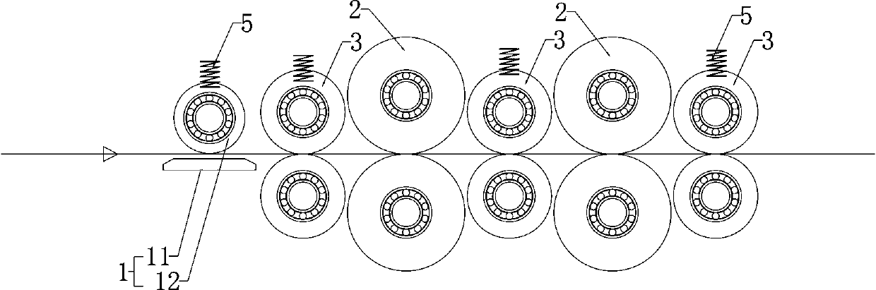
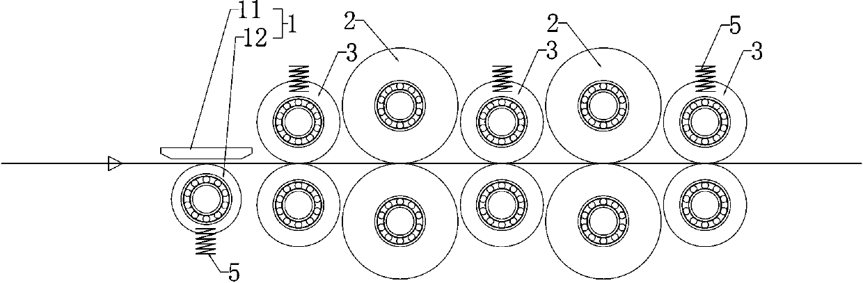
[0021] See attached figure 1 to attach figure 2 As shown, in this embodiment, a non-cooking waste metal paint layer heat removal device includes a thermal paint removal mechanism 1 and a scrubbing brush mechanism in sequence along the conveying direction of waste boards. The thermal paint stripping mechanism 1 of this embodiment is used to heat-treat the slowly fed waste boards, so that the metal part of the waste boards can self-heat. The heated electromagnetic heating unit 11 and the pressure roller 12 made of non-metallic material, the pressure roller 12 of this embodiment can adopt a soft roller surface (such as a rubber roller surface) or a hard roller surface (such as a wooden roller surface). The pressure roller 12 is arranged close to the heating surface of the electromagnetic heating unit 11 so that a gap for the metal plate to pass is formed between the roller surface of the pressure roller 12 and the heating surface, and the width of the gap is equal to or slightl...
Embodiment 2
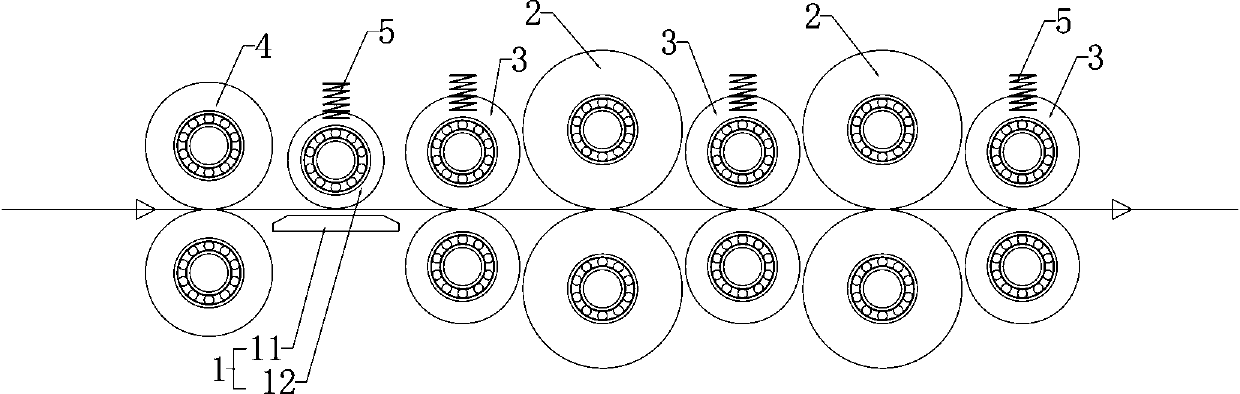
[0028] See attached image 3 to attach Figure 4As shown, the difference compared with Embodiment 1 is that this embodiment also includes a set of feeding rollers located at the inlet end of the thermal stripping mechanism 1, wherein the set of feeding rollers is composed of two flattened feeding rollers that are closely matched to each other. Composed of rollers 4, the roller surfaces of the two flattening and feeding rollers 4 are made of hard materials, and the two flattening and feeding rollers 4 rotate in opposite directions to play the role of pulling and pressing the waste boards, so that the waste boards are flattened to form a flat surface The plate is conveniently sent to the downstream thermal paint stripping mechanism 1 and scrubber mechanism for processing, effectively avoiding the problem of residual paint layer at the raised or bent position caused by the unevenness of the waste plate.
[0029] Further, in any of the two flattening feed rollers 4 of the same gr...
Embodiment 3
[0031] See attached Figure 5 And attached Image 6 As shown, the difference compared with Embodiment 1 and Embodiment 2 is that the thermal paint stripping mechanism 1 of this embodiment includes a heating box and an electromagnetic heating unit 11 that is surrounded by an inner wall of the heating box, wherein the heating box The middle position is formed with a horizontally penetrating hole, and the electromagnetic heating unit 11 ring is set on the inner wall of the hole, so that the waste plate can be buffered and penetrated from the middle position of the heating box, and the electromagnetic heating unit 11 ring is set on the waste plate At the periphery, the electromagnetic heating unit 11 is used to heat the waste boards through ring-shaped electromagnetic induction, thereby further increasing the self-heating rate of the waste boards and accelerating the temperature rise and dissolution of the adhesive surface in the paint layer.
[0032] To sum up, in Embodiment 1, ...
PUM
 Abstract
Description
Claims
Application Information
 - R&D
- Intellectual Property
- Life Sciences
- Materials
- Tech Scout
- Unparalleled Data Quality
- Higher Quality Content
- 60% Fewer Hallucinations
Browse by: Latest US Patents, China's latest patents, Technical Efficacy Thesaurus, Application Domain, Technology Topic, Popular Technical Reports.
© 2025 PatSnap. All rights reserved.Legal|Privacy policy|Modern Slavery Act Transparency Statement|Sitemap|About US| Contact US: help@patsnap.com