Heat-conduction riveting equipment

A technology of heat conduction and riveting, which is applied in the field of heat conduction riveting equipment, can solve the problems of easy-touch heating head, lower production efficiency, and power consumption, and achieve the effects of avoiding wire drawing, improving processing efficiency, and saving energy consumption

Pending Publication Date: 2019-11-12
CHENGDU HOMIN TECH
View PDF0 Cites 2 Cited by
  • Summary
  • Abstract
  • Description
  • Claims
  • Application Information

AI Technical Summary

Problems solved by technology

[0003] However, in the process of lifting the heating head, there will be wire drawing between the heating head and the plastic column, which will affect the quality of the output. After the heating head drops to normal temperature, the worker lifts the heating head up again. Although this method can solve the wire drawing phenomenon, the waiting time is longer, which reduces the production efficiency and is not conducive to mass production.
In addition, the power must be turned on every time to heat the heating head, resulting in more power consumption
In addition, after the metal plate (2) and the plastic plate (1) are installed, it is necessary to manually place the assembled parts under the heating head, and the surrounding temperature of the heating head is particularly high, and the hands are easy to touch the heating head when transferring the parts. Undoubtedly a safety hazard

Method used


Image

  • Heat-conduction riveting equipment
  • Heat-conduction riveting equipment
  • Heat-conduction riveting equipment

Examples


Embodiment Construction

[0018] The present invention will be further described below in conjunction with accompanying drawing, protection scope of the present invention is not limited to the following:

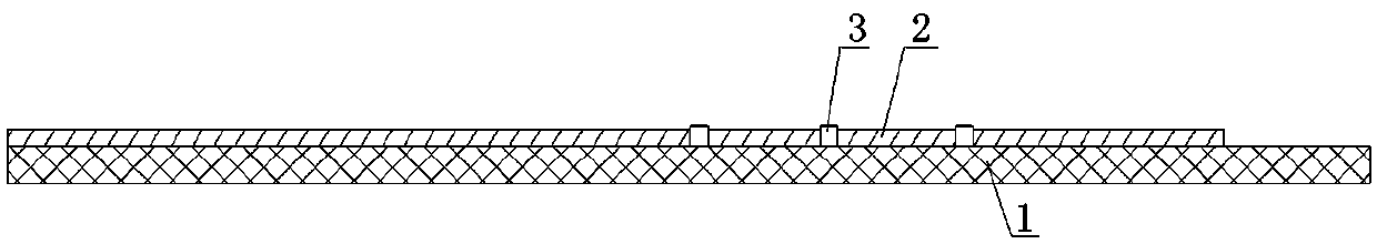
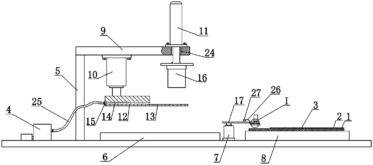
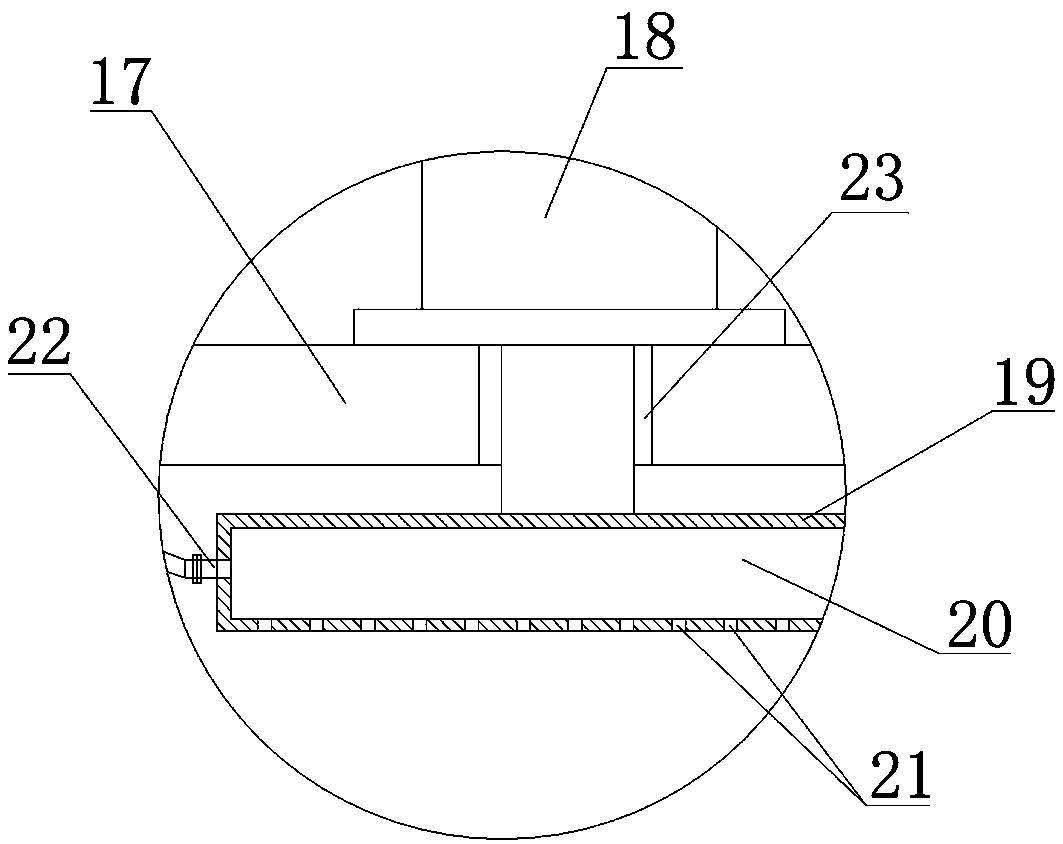
[0019] Such as Figure 2~3 As shown, a heat conduction riveting equipment, which includes an air compressor 4, a frame 5, a workbench 6, a rotary cylinder 7, and a loading table 8 arranged in sequence from left to right, and a crossbeam is arranged on the top of the frame 5 9. The vertical cylinder A10 and cylinder B11 are fixedly installed on the beam 9. The piston rod of the cylinder A10 is provided with an indenter 12, and the right end of the indenter 12 is welded with a horizontally arranged copper sheet 13. The bottom of the copper sheet 13 The surface is flush with the bottom surface of the indenter 12, and the indenter 12 is provided with an airflow passage 14 above the copper sheet 13, the airflow passage 14 is inclined to the right and downwards, and the left end of the airflow passage 14 i...


PUM


Abstract

The invention discloses heat-conduction riveting equipment. The equipment comprises an air compressor (4), a machine frame (5), a workbench (6), a rotating air cylinder (7) and a loading platform (8)which are arranged successively from left to right; the top of the machine frame (5) is provided with a cross beam (9) on which a vertically arranged cylinder A (10) and a cylinder B (11) are fixedlyinstalled, a piston rod of the cylinder A (10) is provided with a pressure head (12), the bottom surface of a copper sheet (13) is flush with the bottom surface of the pressure head (12), the pressurehead (12) is internally provided with an air flow passage (14) formed in the upper portion of the copper sheet (13), the air flow passage (14) tilts down to the right, the left end of the air flow passage (14) is provided with a joint I (15), the joint I (15) is connected with the outlet end of the air compressor (4) through a pipe clamp. The equipment has the advantages of not cutting off a power supply of a heating head, saving energy consumption, improving the processing efficiency, effectively avoiding the occurrence of a drawing phenomenon, and being safe and reliable.

Description

technical field [0001] The invention relates to the technical field of riveting of metal plates and plastic plates, in particular to heat conduction riveting equipment. Background technique [0002] In the production of electronic products, it is necessary to use riveting technology to fix the plastic plate (1) and the metal plate (2) together. figure 1 As shown in the figure, the riveting steps are as follows: First, weld multiple plastic columns (3) on the plastic plate to ensure that the length of the plastic column (3) is slightly greater than the thickness of the metal plate (2), and then set up multiple plastic columns (3) on the metal plate (2). The through hole corresponding to the plastic column (3), the outer diameter of the through hole is slightly smaller than the outer diameter of the plastic column (3), and then the metal plate (2) is sleeved on the plastic column (3) through the through hole to realize The installation of the plastic plate and the metal plate...

Claims


Application Information

Patent Timeline
Patent Type & Authority Applications(China)
IPC IPC(8): B29C65/24B29C65/78B29C65/00
CPCB29C65/24B29C65/7841B29C65/7858B29C66/41
Inventor 杨翠刚李云仕白垣胜石安王银刘仁龙陈建何川
Owner CHENGDU HOMIN TECH
Why Eureka
Try Eureka