
Throttle shaft with axial positioning structure

A throttle shaft and axial positioning technology, applied in engine control, machine/engine, mechanical equipment, etc., can solve problems such as weak axial pressure bearing capacity, throttle sticking or stuck, easy deformation, etc., to achieve increased The effect of improving the service life and stability

Inactive Publication Date: 2019-11-12
温州沃特电气制造厂
View PDF6 Cites 0 Cited by
  • Summary
  • Abstract
  • Description
  • Claims
  • Application Information

AI Technical Summary

Problems solved by technology

[0003] However, in order to ensure the strength and stability of the resin gasket, the thickness of the resin gasket is usually not less than 1mm, resulting in a higher space requirement during assembly; and, after long-term use, the resin gasket will be aging due to As a result, its axial pressure bearing capacity is weak, resulting in easy deformation after axial force, and the throttle valve is stuck or stuck.
Although the surface of the retaining ring is coated with anti-rust paint, when the throttle shaft rotates, the anti-rust paint on the surface is easily worn off and rusted after the open retaining ring rubs against the resin gasket; thus affecting the throttle valve normal work of the body
In addition, the positioning of the throttle shaft through the positioning pin and the groove is not only troublesome in assembly and construction, but also friction will be generated between the positioning pin and the groove due to the axial transmission of the throttle shaft, which will easily cause wear on the throttle shaft and the positioning pin , It is also easy to cause the throttle valve to be stuck or stuck, so a throttle shaft with an axial positioning structure came into being

Method used


Image

  • Throttle shaft with axial positioning structure
  • Throttle shaft with axial positioning structure
  • Throttle shaft with axial positioning structure

Examples


Embodiment Construction

[0023] The following will clearly and completely describe the technical solutions in the embodiments of the present invention with reference to the accompanying drawings in the embodiments of the present invention. Obviously, the described embodiments are only some, not all, embodiments of the present invention. Based on the embodiments of the present invention, all other embodiments obtained by persons of ordinary skill in the art without making creative efforts belong to the protection scope of the present invention.

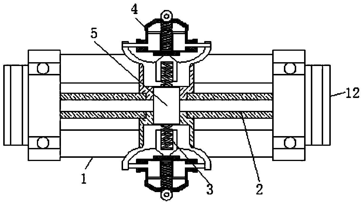
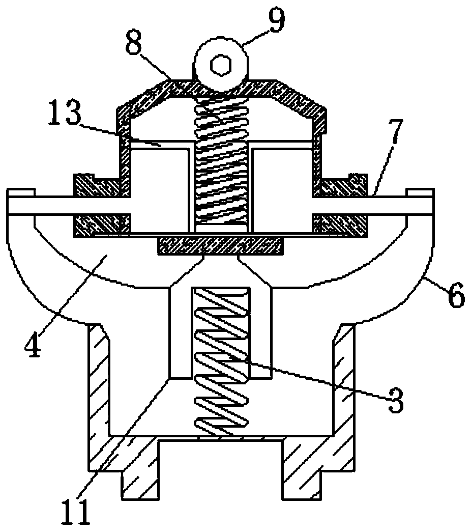
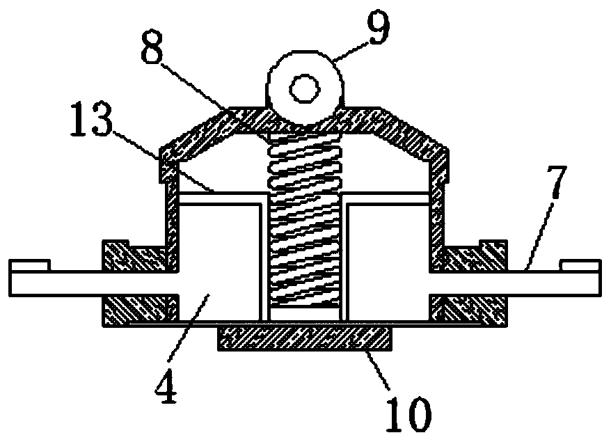
[0024] see Figure 1-7 , a throttle shaft with an axial positioning structure, including a shaft body 1, bearings 12 are fixedly connected to both sides of the shaft body 1, and the bearing 12 is connected to the throttle body conveniently, and the interior of the shaft body 1 is fixedly connected There is a hollow passage 2, and both sides of the hollow passage 2 are movably connected with a compression spring 3, and the surface of the compression spring 3 is...


PUM


Abstract

The invention relates to the technical field of throttle shafts, and discloses a throttle shaft with an axial positioning structure. The throttle shaft comprises a shaft body, a hollow channel is fixedly connected to the interior of the shaft body, compression springs are movably connected to two sides of the hollow channel, and a positioning mechanism is movably connected to the end, away from the hollow channel, of each compression spring. A rotary sleeve is movably connected with the interior of the hollow channel. Each positioning mechanism comprises a supporting frame, wherein exhaust pipes are fixedly connected to two sides of the supporting frame. Airflow entering the positioning mechanisms flows through clamping plates and is discharged from the exhaust pipes, and the diameter of the exhaust pipes is larger than that of the clamping plates, so that a pressure difference is generated by the airflow between the exhaust pipes and the clamping plates, that is, the air pressure of the clamping plates is small and the air pressure of the exhaust pipes is large, then the clamping plates are extruded, limiting pipes can be clamped by the clamping plates, and the situation that rollers generate large extrusion force on a door body and damage the door body can be prevented. Therefore, the effects of improving the stability and prolonging the service life are achieved.

Description

technical field [0001] The invention relates to the technical field of throttle shafts, in particular to a throttle shaft with an axial positioning structure. Background technique [0002] In the throttle body, the throttle shaft is usually provided with an axial positioning device, which is used to control the relative position of the throttle shaft installation, so as to limit the axial movement of the shaft. At present, the axial customization of the throttle shaft is mainly to install a gasket and a retaining ring at one end of the throttle shaft, and a torsion spring at the other end; at the same time, a groove is arranged on the throttle shaft, and a positioning pin is arranged in the groove. The positioning pin is cylindrical, one end of which is fixed on the shaft hole of the body, and the other end extends into the groove; thus, the relative position and position of the throttle shaft are limited by the cooperation of the gasket and the retaining ring, as well as th...

Claims


Application Information

Patent Timeline
Patent Type & Authority Applications(China)
IPC IPC(8): F02D9/10
CPCF02D9/10
Inventor 孙上党冯宪波
Owner 温州沃特电气制造厂
Learn More