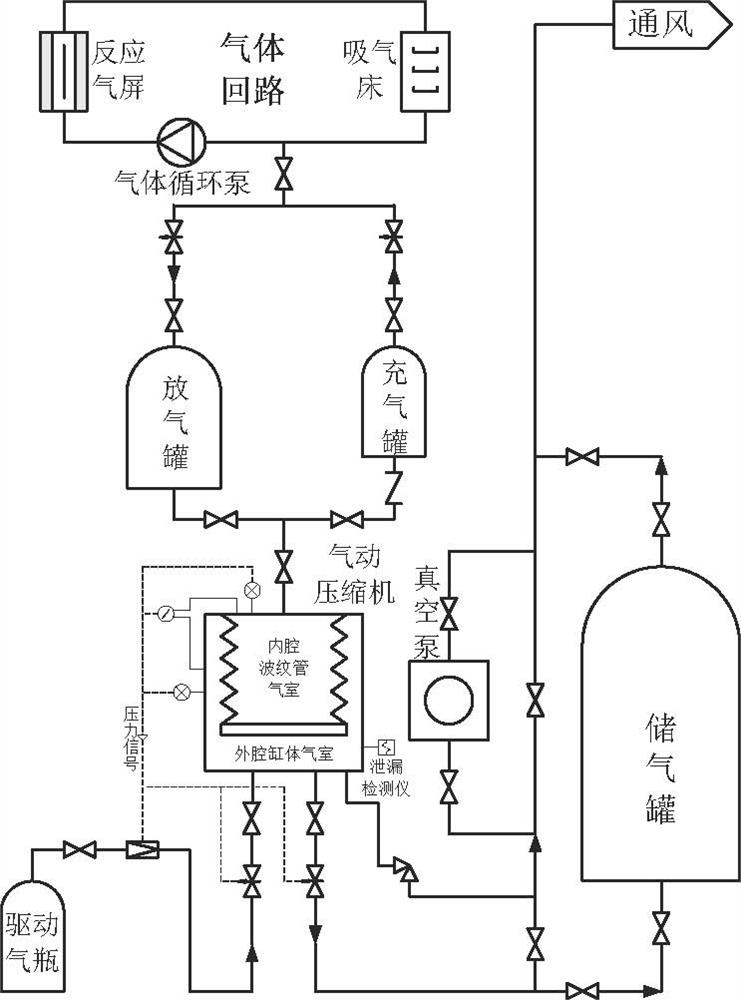
A gas high-tight medium-speed pressure regulation system and method
A pressure regulating system and high sealing technology, applied in the direction of reducing greenhouse gases, climate sustainability, liquid variable capacity machinery, etc., to improve the ability of rapid power transient test, increase irradiated power, improve compression boost and gas The effect of loop drop
- Summary
- Abstract
- Description
- Claims
- Application Information
AI Technical Summary
Problems solved by technology
Method used
Image
Examples
Embodiment 1
[0031] A process flow diagram of a medium-speed high-seal medium-speed pressure regulating system, such as figure 1 shown. The medium-speed pressure-regulating absorption of the present invention is mainly composed of a gas circuit, an inflatable tank, a deflation tank, a pneumatic compressor, a driving gas cylinder, a gas storage tank, a vacuum pump, valves, pipelines and instruments etc. The gas circuit is a high-seal forced circulation circuit formed by connecting the reaction gas shield inside the reactor with the suction bed outside the reactor, gas circulation pump and other equipment. And connect the reaction gas shield through the gas circuit. The inlet and outlet of the bellows air chamber in the inner cavity of the pneumatic compressor are connected with the inlet of the air charging tank and the outlet of the deflation tank, and the air chamber of the outer cavity cylinder is connected with the air intake and exhaust pipes driven by air pressure. The medium-speed...
Embodiment 2
[0036] The difference between this implementation example and Example 1 is that since the pneumatic compressor can only suck 1 / 3 of the process gas from the vent tank at a time into the inner cavity bellows air chamber to compress and pressurize it to the inflatable tank, in order to reduce the residual gas in the vent tank Consumption of expensive process gas in the gas tank, increasing the final pressure of the compressed gas in the gas tank. The present invention uses the air pressure-driven metal bellows diaphragm compressor's repeated rounds of filling and deflation methods to suck and compress the gas in the gas deflation tank, reduce the amount of gas in the deflation tank, and increase the pressure in the gas inflation tank. The specific method is as follows :
[0037]On the basis of Embodiment 1, the medium-speed pressure regulating system of the present invention subsequently closes the communication valve between the pneumatic compressor and the inflation tank, open...
Embodiment 3
[0039] The difference between this implementation example and Embodiments 1 and 2 is that when it is necessary to pump the expensive process gas lower than normal pressure in the deflation tank into the pneumatic compressor for compression, further reduce consumption and improve the process in the inflation tank When the final compression pressure of the gas is reached, the present invention uses a vacuum-driven and air-pressure-driven double-acting metal bellows diaphragm pneumatic compressor to suck the gas in the degassing tank (which may also include a gas circuit and a gas screen), and after compression and boosting Discharge into the inflatable tank, the specific setting method is as follows:
[0040] When the gas pressure in the vent tank is lower than normal pressure, it cannot flow naturally into the pneumatic compressor, and the suction process needs to be converted from air pressure drive to vacuum drive. In order to realize the vacuum drive and suck the expensive p...
PUM
 Abstract
Description
Claims
Application Information
 - R&D
- Intellectual Property
- Life Sciences
- Materials
- Tech Scout
- Unparalleled Data Quality
- Higher Quality Content
- 60% Fewer Hallucinations
Browse by: Latest US Patents, China's latest patents, Technical Efficacy Thesaurus, Application Domain, Technology Topic, Popular Technical Reports.
© 2025 PatSnap. All rights reserved.Legal|Privacy policy|Modern Slavery Act Transparency Statement|Sitemap|About US| Contact US: help@patsnap.com

