High-efficiency low-NOx two-stage self-preheating burner

A two-stage heat exchanger, high-efficiency technology, applied in the direction of burner, combustion method, combustion type, etc., can solve the problems of difficult to meet environmental protection standards, large amount of pollutants, single combustion method, etc., to reduce control costs, exchange The effect of large thermal coefficient and simple control structure

Pending Publication Date: 2019-11-12
FOSHAN KEHAO COMBUSTION EQUIP MFG
View PDF0 Cites 0 Cited by
  • Summary
  • Abstract
  • Description
  • Claims
  • Application Information

AI Technical Summary

Problems solved by technology

However, the combustion mode of the conventional self-preheating burner is single, and the heat exchange efficiency has always been low; at the same time, when the traditional burner structure is used in the conventional combustion mode with high air preheating temperature, the amount of pollutants such as NOx is generated, which is difficult to achieve. Meet environmental standards

Method used


Image

  • High-efficiency low-NOx two-stage self-preheating burner
  • High-efficiency low-NOx two-stage self-preheating burner
  • High-efficiency low-NOx two-stage self-preheating burner

Examples


Embodiment 1

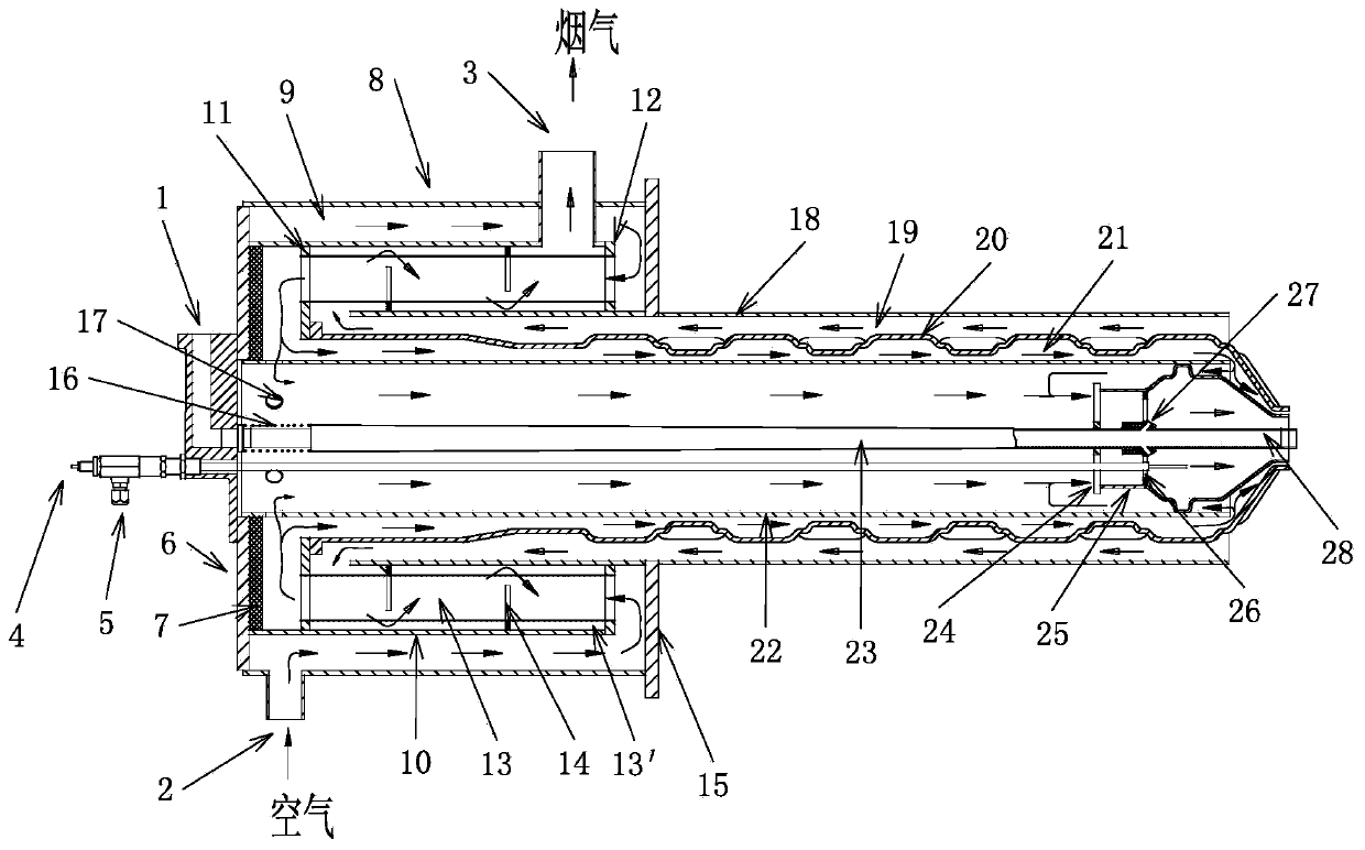
[0044] refer to Figure 1~8, a high-efficiency and low-NOx secondary self-preheating burner, including a housing, an air duct 22, a gas duct 23, a flue gas duct 18, a combustion chamber 25, and a self-cooling electrode 4; 22 on the outside of the rear end of the air housing 8 and the gas housing 6 fixed on the outer surface of the air housing 8, the air housing 8 is provided with an air inlet 2 and a smoke outlet 3, the air inlet 2 and the smoke outlet The relative position of the gas outlet 3 is adjustable to meet applications in different environments. The gas casing 6 is provided with a gas inlet 1, and an insulating lining 7 is arranged between the air casing 8 and the gas casing 6; the gas conduit 23 One end of one end is fitted with a mounting spring 16 and fixed in the air conduit 22 through the mounting spring 16, and communicated with the gas inlet 1 at the same time, the gas conduit 23 is fixed in the air housing 8 through the mounting spring 16, and can be installed...

Embodiment 2

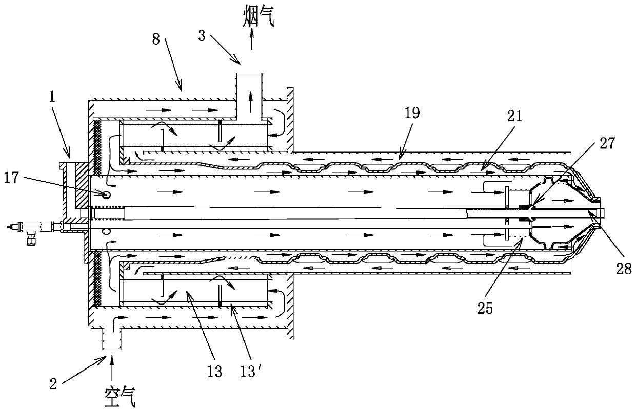
[0061] refer to Figure 12~17 , the structure of this embodiment is basically the same as that of Embodiment 1, the difference is that: the gas pipe 23 is provided with a gas pipe 31, one end of the gas pipe 31 extends to the outside of the housing, and the gas pipe 23 and the gas pipe 31 are both The gas supply equipment is connected separately, so that one of the gas conduit 23 and the gas pipe 31 can supply gas separately or the gas conduit 23 and the gas pipe 31 can supply gas simultaneously. Further, the channel member 33 is a heat exchange conduit, and the two ends of the heat exchange conduit are respectively connected to the first flange 11 and the second flange 12, and the heat exchanger channel I13 is formed by the circular lumen of each heat exchange conduit , that is, the cross-sectional shape of a single heat exchanger channel I13 is circular, and the heat exchange pipe can be made of any one of straight pipe, spiral pipe, surface-shaped treatment pipe and finned ...

Embodiment 3

[0069] refer to Figure 18 , the structure of this embodiment is basically the same as that of Embodiment 2, the difference is that: the secondary heat exchanger 10 does not include a shell, and the secondary heat exchanger 10 includes a first flange 11, a second flange 12, several parallel arrangement The bypass baffle 14 and the channel member 33, the channel member 33 is a heat exchange conduit, the heat exchange conduit runs through the bypass baffle 14, the first flange 11 and the second flange 12 are sleeved on the surface of the air conduit, And fixed on both ends of the air shell 8, the flow-around baffles 14 are fixed in the air shell 8 and distributed alternately along the extending direction of the air shell 8, and one end of the heat exchange conduit is fixedly arranged on the first flange 11 The other end of the heat exchange pipe is fixed on the second flange 12 . And in concrete implementation, must add thermal insulation liner 7 on the inner wall of air shell ...


PUM


Abstract

The invention relates to a high-efficiency low-NOx two-stage self-preheating burner comprising a shell, an air guide pipe, a gas guide pipe, a flue gas guide pipe, a combustion chamber and a self-cooling electrode. An air inlet, a flue gas outlet and a gas inlet are formed in the shell, the gas guide pipe is fixed in the air guide pipe and communicates with the gas inlet, the air guide pipe is sleeved with a primary heat exchanger matched with the air guide pipe to form an air passage, the flue gas guide pipe is arranged on the surface of the primary heat exchanger in a sleeving manner to forma flue gas passage communicating with the flue gas outlet, the shell is internally provided with a secondary heat exchanger installed on the surface of the air guide pipe in a sleeving manner, the secondary heat exchanger is provided with a plurality of heat exchanger passages I and a heat exchanger passage II communicating with the flue gas passage, and the two ends of each heat exchanger passage I are in communication with the air inlet and the air passage. The high-efficiency low-NOx two-stage self-preheating burner can perform two-stage heat exchange on air, the heat exchange efficiency is effectively improved, the temperature of the preheated air is improved to the greatest extent, the air is fully preheated by utilizing waste heat of flue gas, the combustion efficiency is improved,and the energy saving level of the self-preheating burner us greatly improved.

Description

technical field [0001] The invention relates to the structure of a self-preheating burner, in particular to a high-efficiency and low NOx secondary self-preheating burner. Background technique [0002] Industrial production activities are the main cause of energy and environmental problems. Industrial furnaces and other equipment are the main source of air pollution and are also high energy-consuming industrial equipment. As one of the most important devices in industrial furnaces, burners directly determine the energy consumption and pollutant emissions of industrial furnaces. The self-preheating burner is a typical type of industrial furnace burner. The burner acts as a combustion device and a smoke exhaust device at the same time. However, the combustion mode of the conventional self-preheating burner is single, and the heat exchange efficiency has always been low; at the same time, when the traditional burner structure is used in the conventional combustion mode with hi...

Claims


Application Information

Patent Timeline
Patent Type & Authority Applications(China)
IPC IPC(8): F23D14/02F23D14/46F23D14/62F23D14/66
CPCF23D14/02F23D14/46F23D14/62F23D14/66Y02E20/34
Inventor 王建中吕永超潘映沛颜磊宋付志宋晓敏谢明勇魏长鸿
Owner FOSHAN KEHAO COMBUSTION EQUIP MFG
Why Eureka
Try Eureka