Uniaxial bidirectional synchronous control and electromagnetic loading dynamic shear test device and test method

A synchronous control, uniaxial and bidirectional technology, applied in the direction of testing material strength by applying stable shear force, testing material strength by applying repetitive force/pulsation force, testing material strength by applying stable tension/pressure, etc., to achieve test The effect of reliable results and shortening the dynamic shear stress equilibrium time

Pending Publication Date: 2019-11-12
SHENZHEN UNIV
View PDF0 Cites 16 Cited by
  • Summary
  • Abstract
  • Description
  • Claims
  • Application Information

AI Technical Summary

Problems solved by technology

[0003] Purpose of the invention: In order to solve the problem that existing experimental devices and testing methods cannot carry out larger-scale (such as sample length × width = 150mm*100mm) rock materials at high strain rates (10 mm) that are close to actual conditions. 1 ~10 3 the s -1 ) The technical problems of dynamic shear mechanic...

Method used


Image

  • Uniaxial bidirectional synchronous control and electromagnetic loading dynamic shear test device and test method
  • Uniaxial bidirectional synchronous control and electromagnetic loading dynamic shear test device and test method
  • Uniaxial bidirectional synchronous control and electromagnetic loading dynamic shear test device and test method

Examples


Embodiment approach 1

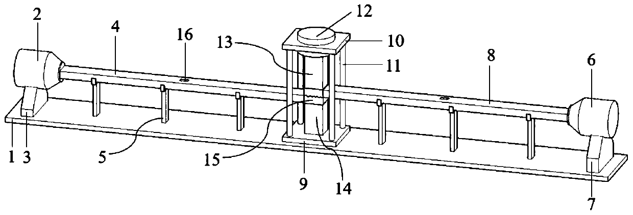
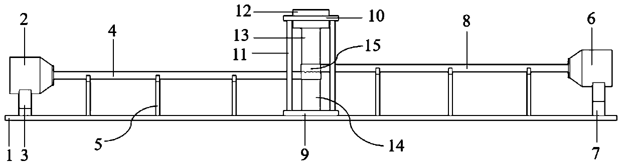
[0041] figure 1 It is a three-dimensional diagram of a single-axis bidirectional synchronous control electromagnetic loading dynamic shear test device, including a support platform, a loading rod system, an electromagnetic pulse emission system, a normal pressure servo control loading system, and a data monitoring and acquisition system. The test device is centered on the test sample 15 and arranged on its left and right sides. The left dynamic shear loading device includes the left electromagnetic pulse excitation cavity 2, the left electromagnetic pulse excitation cavity support 3, and the left stress wave loading rod 4. And the stress wave loading rod support 5, wherein the left electromagnetic pulse excitation cavity 2 is placed on the left electromagnetic pulse excitation cavity support 3, the left electromagnetic pulse excitation cavity 2 and the left electromagnetic pulse excitation cavity support 3 can be supported The platform 1 moves axially along the loading bar and...

Embodiment approach 2

[0049]Place the processed and polished cube red sandstone (i.e. test sample 15) with a length, width, and height of 100mm on the center of the surface of the base 14, and place a TC21 titanium alloy with a length of 2m, a width of 100mm, and a height of 50mm. The left stress wave loading rod 4 is placed flat in the slot of the stress wave loading rod support 5, and it is ensured that the left stress wave loading rod 4 can freely slide left and right in the slot, and then the left stress wave loading rod 4 The right loading end face of the cube red sandstone (ie test sample 15) is aligned with the lower half section of the left dynamic shear loading surface and fully fitted together, and the left electromagnetic pulse excitation cavity 2 is placed on the left electromagnetic pulse The pulse excitation chamber support 3, and adjust both to the end of the left stress wave loading rod 4, so that the right stress wave output end surface of the left electromagnetic pulse excitation c...

Embodiment approach 3

[0053] Place the processed and polished granite with a single joint surface (i.e. test sample 15) with a length, width, and height of 200mm, 100mm, and 100mm respectively on the center of the surface of the base 14. The length is 2m, and the width and height are respectively The 100mm and 50mm TC21 titanium alloy left stress wave loading rod 4 is placed flat in the slot of the stress wave loading rod support 5, and the left stress wave loading rod 4 can slide freely in the slot. The right loading end surface of the left stress wave loading rod 4 is aligned with the lower half section of the left dynamic shear loading surface of the granite with a single joint surface (ie, the test sample 15) and fully fitted together. The electromagnetic pulse excitation cavity 2 is placed on the support 3 of the left electromagnetic pulse excitation cavity, and the two are adjusted to the end of the left stress wave loading rod 4, so that the right stress wave output end surface of the left el...


PUM

PropertyMeasurementUnit
Elastic modulusaaaaaaaaaa

Abstract

The invention provides a uniaxial bidirectional synchronous control and electromagnetic loading dynamic shear test device and test method. The uniaxial bidirectional synchronous control and electromagnetic loading dynamic shear test device comprises a support platform, a loading rod part system, an electromagnetic pulse transmission system, a normal pressure servo control loading system and a datamonitoring and acquisition system. On the basis of the test device, dynamic shear test study of rock materials can be carried out under constant normal pressure under the conditions close to the actual work conditions, and complete rock samples with different test sizes or joint rock samples with single structure surfaces can be selected according to test demands to carry out study of dynamic shear mechanical characteristics and shear damage rules under the condition that the strain rate is 10<1>-10<3> s<-1>, so that important theoretical basis and technique support are provided for design, construction, protection and safety and stability evaluation of rock engineering, structure engineering and the like.

Description

technical field [0001] The invention belongs to the field of research on dynamic shearing mechanical properties and rupture laws of solid materials or structural surfaces. More specifically, it relates to a uniaxial bidirectional synchronous control electromagnetic loading dynamic shear test device and test method for the study of dynamic shear strength and dynamic shear failure law of solid materials such as rocks, concrete, polymers or structural surfaces. Background technique [0002] Understand and master the shear mechanical properties and shear failure laws of solid materials, especially rock and concrete materials, for the design, construction, operation, safety and stability evaluation of modern large-scale civil engineering such as construction engineering, structural engineering and rock engineering plays a very important role. At present, the methods used to test the shear mechanical properties and failure laws of rock materials are mainly direct shear tests base...

Claims


Application Information

Patent Timeline
IPC IPC(8): G01N3/317G01N3/06G01N3/24
CPCG01N3/317G01N3/068G01N3/24G01N2203/0025G01N2203/001G01N2203/005G01N2203/0075G01N2203/0067G01N2203/0064G01N2203/0066G01N2203/0676G01N2203/0641G01N2203/0252G01N2203/0647G01N3/10G01N3/32G01N29/11G01N2291/0232G01N29/2412G01N2291/02827G01N3/38G01N35/00871
Inventor 朱建波谢和平周韬高明忠李存宝廖志毅王俊张凯
Owner SHENZHEN UNIV
Why Eureka
Try Eureka