Machining fixture for turnover bracket

A technology for flipping brackets and fixtures, applied in the directions of manufacturing tools, metal processing equipment, auxiliary devices, etc., can solve the problems of lack of welding fixtures and inaccurate positioning in welding workshops, and achieve improved functional structure, simple device structure, and improved functionality. Effect

Inactive Publication Date: 2019-11-15
十堰市弘康汽配科技有限公司
View PDF1 Cites 1 Cited by
  • Summary
  • Abstract
  • Description
  • Claims
  • Application Information

AI Technical Summary

Problems solved by technology

[0004] Based on the tooling in the above example file, it is used to assemble and install the flip bracket that provides the shape, not the tooling when the flip bracket itself is welded. However, the flip bracket product it mentions is different from the flip bracket that this design will describe The structure and application of bracket products are basically the same. Based on the above examples, the designer found that because the existing flip bracket is composed of a bottom welding plate and two lug plates welded on the bottom welding plate, the actual welding process , the welding workshop lacks a reasonable and simple welding fixture. When the cylinder bracket is welded to it by the two lifting lugs on the bottom welding plate, the positioning is not accurate. Therefore, it is necessary to design a structure that is both simple and convenient to make the two lifting lugs The tooling where the vertical plate is welded on the bottom plate is used to complete the spot welding butt joint of the flip bracket of the welding product and to increase its welding speed

Method used


Image

  • Machining fixture for turnover bracket
  • Machining fixture for turnover bracket
  • Machining fixture for turnover bracket

Examples


Embodiment

[0029] as attached figure 1 to attach Figure 7 Shown:

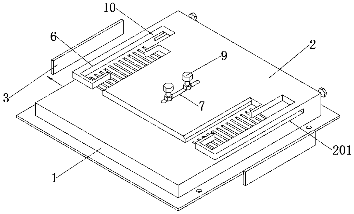
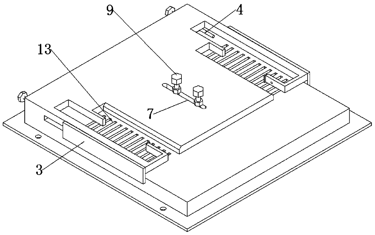
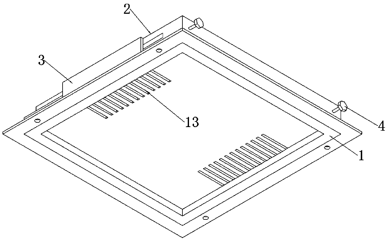
[0030] The invention provides a processing jig for a flip bracket, which includes a mounting base 1, a pressure plate 2, a pressure groove 201, a limit plate 3, a top bolt 4, a notch 5 in the left welding area, a notch 6 in the right welding area, and a middle notch 7 , welding nut 8, locking bolt 9, left vertical plate welding limit groove 10, right vertical plate welding limit groove 11, wipe seat 12 and drain groove 13; the mounting seat 1 is a square cavity structure, and its bottom surface has The mounting plate of the mounting hole; the top surface of the mounting seat 1 is provided with an upwardly tilted pressure plate 2, and the pressure plate 2 is parallel to the top surface of the mounting seat 1; the middle position of the pressure plate 2 is provided with a waist circular notch structure The middle notch 7, and two welding nuts 8 are welded on the middle notch 7, and two locking bolts 9 are threaded downwa...


PUM


Abstract

The invention provides a machining fixture for a turnover bracket. The machining fixture for the turnover bracket comprises wiping seats and leaking slots; an installation seat is of a square cavity structure, and an installation plate with installation holes is arranged on the bottom surface of the installation seat; a cocked pressing plate is arranged on the top surface of the installation seat,and the pressing plate is parallel to the top surface of the installation seat; and a middle notch of a kidney circular notch structure is formed in the middle position of the pressing plate, two welded nuts are welded to the middle notch, two lock-pressing bolts are arranged downwards in a screw-thread fit mode through the two welded nuts, a welded notch area corresponding to stand plate clamping slots is arranged, spot welding can be conveniently carried out when stand plates constituting the turnover bracket are in butt joint with a bottom constituting the turnover bracket, the wiping seats are installed on notches of the welded notch structure and clamping slot structure areas, the wiping seats are used for wiping off oxide skin welding slag beat by welding spots when the turnover bracket after spot welding is pulled out outwards, the oxide skin welding slag leaks outwards through the leaking slots, and a functional structure is improved.

Description

technical field [0001] The invention belongs to the technical field of clamp structures, and more specifically relates to a processing clamp for a flip bracket. Background technique [0002] The bottom of the truck cab is equipped with a rotating bracket. The installed rotating bracket is used to hang or support the oil cylinder. It supports and angles the oil cylinder when it moves. When the oil cylinder action rod is stretched out, the car can be driven. The top of the chamber rotates dynamically, and the overturn bracket used for hanging or supporting the oil cylinder is exactly what this design will describe. [0003] Chinese patent application number CN201821728303.5 discloses a tooling with stable automatic installation for a flip bracket, including a fixed block, an anti-friction pad and a base, a rubber block is installed inside the fixed block, and the inner surface of the rubber block is connected There is a hydraulic cylinder, the fixed block and the rubber block...

Claims


Application Information

Patent Timeline
Patent Type & Authority Applications(China)
IPC IPC(8): B23K37/04B23K37/00
CPCB23K37/00B23K37/0443
Inventor 罗红袁愿刘军
Owner 十堰市弘康汽配科技有限公司
Why Eureka
Try Eureka